EasyManua.ls Logo

Heat & Glo 6000G User Manual

Heat & Glo 6000G
71 pages
To Next Page IconTo Next Page
Page #1 background imageLoading...
Page #1 background image
Heat & Glo • 6000G, 6000G-IPI • 2103-900 Rev. M • 9/08 1
Models:
6000G
6000G-LP
6000G-IPI
6000G-IPILP
Do not store or use gasoline or other am-
mable vapors and liquids in the vicinity of
this or any other appliance.
What to do if you smell gas
- Do not try to light any appliance.
- Do not touch any electrical switch. Do not
use any phone in your building.
- Immediately call your gas supplier from a
neighbor’s phone. Follow the gas suppli-
er’s instructions.
- If you cannot reach your gas supplier, call
the re department.
Installation and service must be performed
by a quali ed installer, service agency, or the
gas supplier.
WARNING: If the information in these
instructions is not followed exactly, a re
or explosion may result causing property
damage, personal injury, or death.
Owners Manual
Installation and Operation
DO NOT DISCARD THIS MANUAL
CAUTION
This appliance may be installed as an OEM installation in
manufactured home (USA only) or mobile home and must be
installed in accordance with the manufacturer’s instructions and
the manufactured home construction and safety standard, Title
24 CFR, Part 3280 or Standard for Installation in Mobile Homes,
CAN/CSA Z240MH.
This appliance is only for use with the type(s) of gas indicated
on the rating plate.
Leave this manual with
party responsible for use
and operation.
DO NOT
DISCARD
• Important operating
and maintenance
instructions included.
Read, understand and follow
these instructions for safe
installation and operation.
Para obtener un ejemplar en Español de este
Manual del propietario, visite www.heatnglo.com.
Pour demander un exemplaire en français de ce Manuel
du propriétaire, visitez www.heatnglo.com.
Installation and service of this appliance should be
performed by quali ed personnel. Hearth & Home
Technologies suggests NFI certi ed or factory trained
professionals, or technicians supervised by an NFI
certi ed professional.
WARNING
In the Commonwealth of Massachusetts installation must be
performed by a licensed plumber or gas tter.
See Table of Contents for location of additional Commonwealth
of Massachusetts requirements.
This appliance has been supplied with an integral barrier
to prevent direct contact with the xed glass panel. DO
NOT operate the appliance with the barrier removed.
Contact your dealer or Hearth & Home Technologies if the
barrier is not present or help is needed to properly install one.
HOT SURFACES!
Glass and other surfaces are hot during
operation AND cool down.
Hot glass will cause burns.
Do not touch glass until it is cooled
NEVER allow children to touch glass
• Keep children away
CAREFULLY SUPERVISE children in same room as
replace.
Alert children and adults to hazards of high temperatures.
High temperatures may ignite clothing or other ammable
materials.
Keep clothing, furniture, draperies and other ammable
materials away.

Table of Contents

Other manuals for Heat & Glo 6000G

Question and Answer IconNeed help?

Do you have a question about the Heat & Glo 6000G and is the answer not in the manual?

Heat & Glo 6000G Specifications

General IconGeneral
BrandHeat & Glo
Model6000G
CategoryIndoor Fireplace
LanguageEnglish

Summary

Listing and Code Approvals

C. BTU Specifications

Lists the maximum and minimum input BTU/h and orifice sizes for different models.

Getting Started

A. Design and Installation Considerations

Covers factors to consider before installation, including codes, location, and utilities.

Framing and Clearances

B. Constructing the Appliance Chase

Details how to build a chase structure to enclose the gas appliance and vent system.

C. Clearances

Specifies required clearances from the appliance to combustible materials.

Termination Locations

A. Vent Termination Minimum Clearances

Details minimum clearances for vent termination caps from roof, walls, and openings.

Vent Information and Diagrams

D. Top Vent - Horizontal Termination Diagrams

Illustrates vent configurations for top vent horizontal terminations with one or two elbows.

E. Top Vent - Vertical Termination Diagrams

Details minimum and maximum vertical vent lengths and flue restrictor instructions.

F. Rear Vent - Horizontal Termination Diagrams

Shows vent configurations for rear vent horizontal terminations with no, one, or two elbows.

G. Rear Vent - Vertical Termination Diagrams

Illustrates vent configurations for rear vent vertical terminations with one, two, or three elbows.

Vent Clearances and Framing

A. Pipe Clearances to Combustibles

Specifies minimum clearances for vent pipes from combustible materials and notes on heat shields.

B. Wall Penetration Framing

Details framing requirements for combustible and non-combustible wall penetrations for venting.

C. Vertical Penetration Framing

Outlines framing requirements for ceiling firestops when penetrating between floors and attics.

Appliance Preparation

C. Securing and Leveling the Appliance

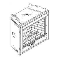
Guides on properly positioning, leveling, and securing the appliance using nailing tabs.

Installing Vent Pipe (DVP and SLP Pipe)

A. Assemble Vent Sections (DVP Pipe Only)

Steps for assembling DVP vent sections, including sealing for commercial applications.

B. Assemble Vent Sections (SLP Pipe Only)

Steps for assembling SLP vent sections, including sealing for commercial applications.

M. Install Horizontal Termination Cap (DVP and SLP Pipe)

Instructions for installing horizontal termination caps, including overlap and flashing guidelines.

Gas Information

C. Gas Connection

Provides guidance on connecting the gas supply line according to local codes and standards.

Electrical Information

C. Intellifire Ignition System Wiring

Details wiring requirements for the Intellifire ignition system, including battery pack and transformer.

D. Standing Pilot Ignition System Wiring

Explains wiring for the Standing Pilot Ignition system and its power requirements.

Appliance Setup

Operating Instructions

B. Lighting Instructions (IPI)

Provides step-by-step instructions for lighting the appliance with an Intermittent Pilot Ignition system.

B. Lighting Instructions (Standing Pilot)

Provides step-by-step instructions for lighting the appliance with a Standing Pilot Ignition system.

Troubleshooting

A. Standing Pilot Ignition System

Guides a technician through diagnosing and correcting issues with the standing pilot ignition system.

B. Intellifire Ignition System

Assists technicians in diagnosing and resolving problems with the Intellifire ignition system.

Maintaining and Servicing Appliance

A. Maintenance Tasks

Outlines routine maintenance tasks and safety precautions before and after servicing.

A. Maintenance Tasks Checklist

Provides a detailed checklist for inspecting and cleaning various components of the appliance.

Service Parts

C. Service Parts List

Comprehensive list of available service parts for the appliance, including part numbers.

Related product manuals