Do you have a question about the Heat Controller B-DVH09SD-0 and is the answer not in the manual?
Essential safety guidelines to prevent injury and property damage during handling and operation.
Critical warnings regarding installation, operation, and product usage to avoid hazards.
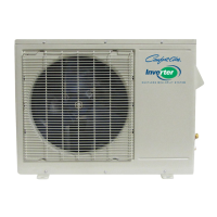
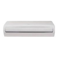
Lists model numbers for indoor and outdoor units based on capacity.
Specifies minimum clearances for indoor and outdoor unit installation.
Detailed explanations of various unit features and their operational functions.
Provides physical dimensions for the indoor unit, including W, D, and H.
Details dimensions and specifications for the indoor unit mounting bracket.
Provides physical dimensions for the outdoor unit, including W, H, D, W1, A, and B.
Illustrates the refrigerant flow diagram for cooling-only DVC models.
Illustrates the refrigerant flow diagram for heat pump DVH models.
Shows the electrical wiring configurations for various indoor units.
Shows the electrical wiring configurations for various outdoor units.
Outlines electrical codes and requirements for proper installation.
Specifies the required sizes for gas and liquid refrigerant line sets.
Provides guidance on adding refrigerant for field-installed line sets.
Lists abbreviations used for temperature sensors and display indicators.
Identifies icons and their meanings on the indoor display board.
Details various protection mechanisms for the compressor and inverter module.
Describes the operation of the fan-only mode, excluding cooling/heating.
Explains compressor and fan operation during cooling mode.
Explains compressor and fan operation during heating mode.
Details the conditions and process for defrost mode operation.
Explains how the unit automatically selects modes based on temperature.
Details the operation of the unit in dry mode, focused on dehumidification.
Explains the setup and operation of the timer functions for scheduling.
Describes the automatic temperature adjustments made during sleep mode.
Lists and explains error codes displayed by the indoor unit.
Discusses common errors and troubleshooting steps for outdoor units.
Provides diagnostic procedures and solutions for various error codes.
Presents pressure readings for cooling mode under different conditions.
Presents pressure readings for heating mode under different conditions.
| Cooling Capacity (BTU) | 9000 |
|---|---|
| HSPF | 10 |
| Refrigerant | R410A |
| Voltage (V) | 208-230 |
| Power Supply | 1-phase, 60Hz |