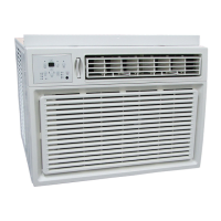
Do you have a question about the Heat Controller MSS-024B/A and is the answer not in the manual?
Describes how to turn the unit on/off using the remote.
Details room temperature sensing and control mechanisms.
Explains safety delays for fan, compressor, and reversing valve.
Covers indoor fan speed options and airflow direction settings.
Details Soft Dry, Sleep Mode, Auto Air, Defrost, and Hot-Start controls.
Covers ON/OFF, Mode Selection, and Fan Speed settings.
Details setting and canceling timers and activating sleep mode.
Covers airflow direction, fan operation, and reset functions.
Provides dimensional details for the indoor unit.
Provides dimensional details for the outdoor unit.
Illustrates the refrigeration cycle for cooling-only units.
Illustrates the refrigeration cycle for cooling and heating units.
Shows wiring diagrams for indoor units.
Shows wiring diagrams for outdoor units (Cooling Only & Heating).
Explains safety delays for compressor, fan, and reversing valve.
Details how to set the vertical louver position or swing.
Describes operation during cooling mode based on intake air temp.
Explains automatic operation based on room and intake air conditions.
Details the operation and temperature settings for Soft Dry mode.
Describes how the unit operates in heating mode.
Explains how defrost operation is controlled by timer and temperature.
Describes operation during Sleep Mode in Cooling or Heating.
Covers forced operation and crank case heater control.
Details test operations for the indoor unit.
Details test operations for the outdoor unit.
Explains indicators and sounds for operation status.
Describes error codes and corresponding unit operations.
Covers warnings, safety precautions, and handling guidelines.
Lists installation parts, selects locations, and covers piping length/elevation.
Details mounting, drilling, piping prep, connection, and insulation for the indoor unit.
Covers connecting outdoor unit pipings, electrical cables, and wiring details.
Covers drainage checks, cable connections, air purging, evacuation, and performance evaluation.
Explains the name and function of each button for cooling mode.
Explains the name and function of each button for heating mode.
Details steps for disassembling 9k, 12k indoor units.
Details steps for disassembling 18k, 24k indoor units.
Analyzes operational issues based on temp difference and current.
Diagnoses issues like unit not operating or remote control problems.
Troubleshoots compressor, fan, and louver operation issues.
Addresses communication errors and connection issues.
Details the main PWB assembly for indoor units and optional functions.
Details the main PWB assembly for outdoor units and optional functions.
Shows the display PWB assembly for different models.
Provides the schematic diagram for the indoor unit.
Provides the schematic diagram for the outdoor unit.
Shows exploded view and lists parts for 9k, 12k indoor units.
Shows exploded view and lists parts for 18k, 24k indoor units.
Shows exploded view and lists parts for 9k, 12k outdoor units.
Shows exploded view and lists parts for 18k outdoor units.
Shows exploded view and lists parts for 24k outdoor units.
| Brand | Heat Controller |
|---|---|
| Model | MSS-024B/A |
| Category | Air Conditioner |
| Language | English |


 Loading...