EN • 20
ENGLISHFRANCAISNEDERLANDSESPAÑOLITALIANODEUTSCH
664Y2800.B
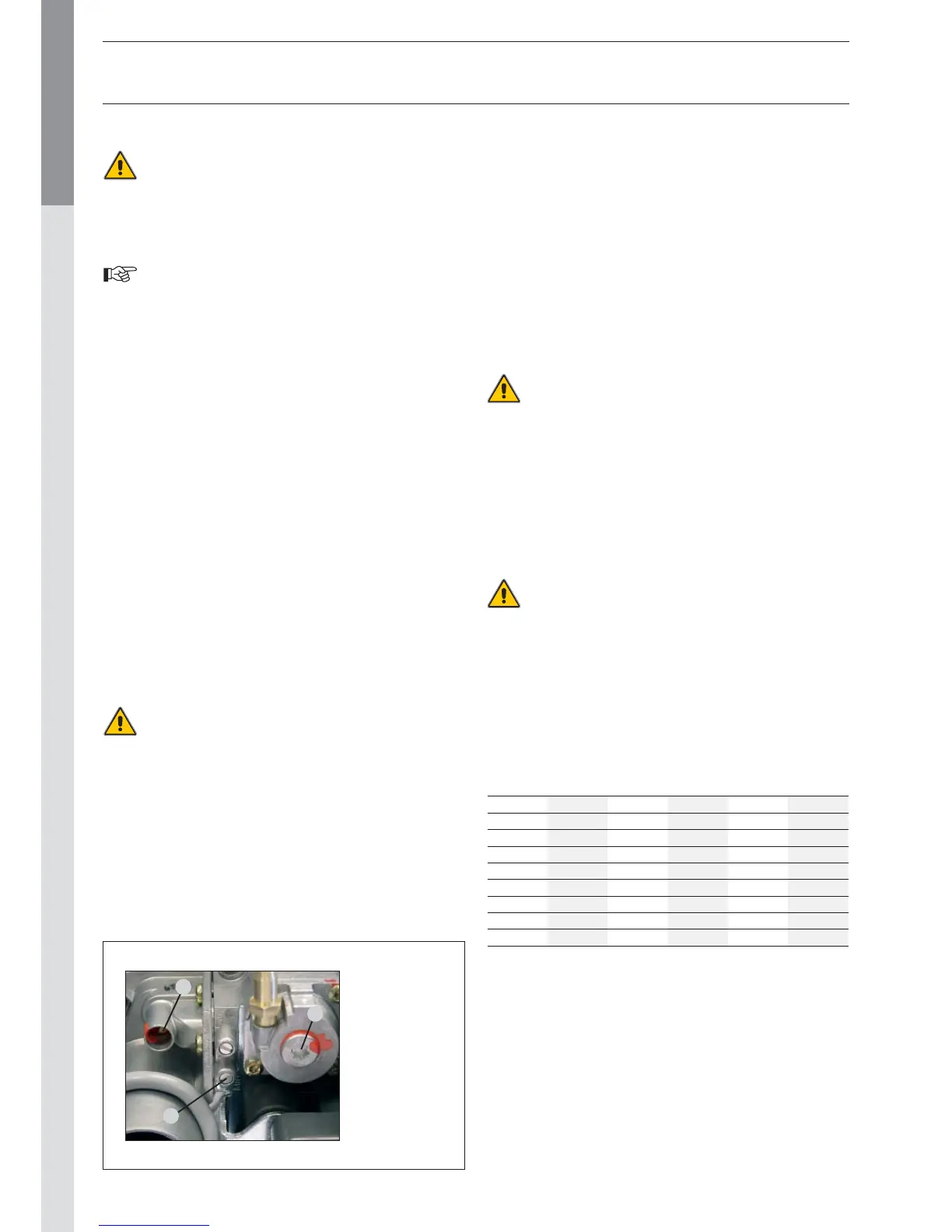
Réf. 3:
The gas valve
offset setting is
a sealed factory
setting.
In principle,
it may not be
modified.
2
1
3
COMMISSIONING THE SYSTEM
Before pressurising the central heating circuit
(primary) you should first pressurise the domestic hot
water tank (secondary).
Both the domestic hot water tank and the central
heating circuit must be filled before using the boiler.
- Slowly fill the tank and drain it by opening a hot water tap. Drain
all the taps and check that there are no leaks in the domestic
hot water system.
- Fill the whole system up to a minimum pressure of 1 bar
(preferably 1.5 bar), using the boiler’s fill valve. Fill the system
slowly. Also check that the automatic air vent on the tank is
working. Check that there are no leaks in the central heating
system.
- Vent the shunt pump and unblock it if necessary.
- Open the gas tap, drain the pipe and check that there are no
leaks in the system.
- Place the condensing trap on the bottom face of the boiler and
check it is fill with water.
- Connect the plug to the wall socket and power on the appli-
ance. If needed, place the room thermostat to its highest
position. The boiler should start. Check the gas pressure and
allow the boiler to heat up for a few minutes. Set the boiler
to High Power mode and check the CO2 level (see the table
of Technical Characteristics)
. Then, set the boiler to Low Power
mode and check the CO2 level again (see the table of Technical
Characteristics)
.
- Set the central heating and hot water temperatures following
the values given in the Directions for Use.
- Drain the central heating system again and, if necessary, re-fill it.
- Make sure the central heating system is correctly balanced
and, if necessary, adjust the valves to prevent a greater or
lesser flow than planned to some circuits or radiators.
The condensate flow pipe diameter can not be decreased.
Moreover this pipe can never be blocked.
CHECKING THE SETTINGS
- Check that the parameters are set in accordance with the
user’s needs: see page 3, Directions for Use.
- Check the boiler settings: this task can only be carried out by an
ACV-trained installer or by the ACV maintenance department.
- Set the appliance to High Power mode by simultaneously pressing
the mode and Plus keys.
COMMISSIONING AND MAINTENANCE
- Check the dynamic gas pressure at the gas valve (see diagram
below, ref. 1)
. This must be at least 18 mbars. Wait a few min-
utes for the appliance to heat up to a minimum temperature of
60°C. Check the CO2 setting using a measurement instrument.
Please see in the Technical Characteristics for optimum value.
To increase the CO2 value, turn the venturi screw counterclockwise;
turn it clockwise to reduce the value (see diagram below ref. 2).
Then put the appliance to High Power mode by simultaneously
pressing the mode and Plus keys. Wait a few minutes to stabilise.
Check the CO2 value. It should be either equal to the full power
value or a maximum of 0.5% less than this value. If you record
a significant deviation,please contact the ACV maintenance
department.
INSPECTION AND MAINTENANCE
ACV recommends that you have your boilers inspected
and cleaned if need be at least once a year.
Plug out the appliance before undertaking any work, even if only
recording measurements and adjusting the settings.
- Check that the condenstrap is not fouled, fill it, if need be, and
check that there are no leaks.
- Check that the safety valves are operating correctly.
- Drain the whole system and if necessary re-fill the appliance to
pressure of 1.5 bar.
If you have to refill your circuit more than twice a year,
please contact your installer.
- Check the boiler charge in High Power mode. If there is a
big difference between this value and the original setting, the
deviation could mean a blockage in the air intake pipes or flue
gas extraction pipes, or that the exchanger has become fouled
with an accumulation of dirt.
TEMPERATURE SENSOR RESISTANCE TABLES
T° [°C] R Ω T° [°C] R Ω T° [°C] R Ω
- 20 98200 25 12000 70 2340
- 15 75900 30 9800 75 1940
- 10 58800 35 8050 80 1710
- 5 45900 40 6650 85 1470
0 36100 45 5520 90 1260
5 28600 50 4610 95 1100
10 22800 55 3860 100 950
15 18300 60 3250
20 14700 65 2750
 Loading...