Do you have a question about the HEIDENHAIN SE 660 and is the answer not in the manual?
Mounting and commissioning must be performed by qualified specialists following local safety regulations.
User information for FCC compliance, including sections 15.19, 15.21, and 15.105.
Declaration of conformity with EU directives for the SE660.
Compliance with Industry Canada license-exempt RSS standards.
Detailed physical dimensions and specified tolerances for the device.
First step in mounting the device, referencing part ID 744677-01.
Second step in mounting, showing connection with torque adapter.
Specifies the minimum clearance required from metallic surfaces.
Details on activation, transmission, touch probe, and pairing for different modes.
Important warning about electronic recentering after switching between IR and RF modes.
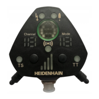
Explains the meaning of green, orange, and red indicators for signal quality.
Interpretation of channel load indicators: free, partially assigned, fully assigned.
Displays indicating the status of TS, TT, or output.
Displays indicating touch probe readiness and battery warnings.
Explains blinking and shining indicators for connection status.
Explains indicators for errors and collisions.
How to use the "Channel" button for next channel selection.
How to use the "Mode" button for mode/slot number changes.
How to pair devices using both "Channel" and "Mode" buttons.
How to delete pairings using both buttons.
Press and hold the "Mode" button until the display blinks.
Tap the "Mode" button until the desired mode appears.
Press and hold the "Mode" button until blinking stops to save the mode.
Press and hold the "Channel" button until the display blinks.
Tap to find the optimum channel, referring to the table on page 17.
Press and hold the "Channel" button until blinking stops to save the channel.
Set touch probe to radio mode, insert batteries, and close.
Press both buttons until "Cn" blinks.
Units connect automatically, indicated by "Cn" illumination.
Steps 1-5 for connecting the first TS/TT unit.
Steps 1-5 for connecting the second TS/TT unit.
Indication for connecting additional TS/TT units.
Steps for initiating connection and selecting/changing slots.
Saving settings, closing the device, and interpreting connection status.
Detailed pin layout for the -01 and -02 versions of the device.
Definitions for signals like Start, Ready, Trigger, and Battery Warning.
Instruction not to use vacant pins or wires.
Displays indicating selection line status (open, standard, etc.).
Displays showing the number of the selected slot.
Technical data for cables, connectors, and maximum lengths.
Specifies bending radius requirements for cables.
Specifies minimum distances from sources of interference.
| Brand | HEIDENHAIN |
|---|---|
| Model | SE 660 |
| Category | Measuring Instruments |
| Language | English |