Do you have a question about the HEIDENHAIN TNC 426CB and is the answer not in the manual?
Explains the causes for specific minor error messages like 'Operating parameters erased' and 'Limit switch'.
Lists general blinking error messages like 'TNC operating temp. exceeded' and their causes.
Details blinking error messages related to the PLC editor and their classifications.
Lists blinking errors related to the position encoder interface and their causes.
Lists blinking errors related to the speed encoder interface and their causes.
Details blinking errors related to analogue axes and their causes, including error location.
Details blinking errors related to digital axes and their causes, including error location.
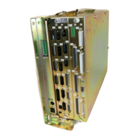
Details the designation of logic unit LE 426 PB/430 PA, showing component labels.
Provides an overview of hardware components for different logic unit models.
Details connectors and pin layouts for the LE 426.B/430.A logic unit.
Shows pin layout for the NC power supply of LE 426 logic units.
Details pin layout for the processor board of LE 426 logic units.
Details pin layout for the V.24/RS-232-C data interface.
Details pin layout for the V.11/RS-422 data interface.
Details pin layout for the serial handwheel connector.
Details pin layout for the PLC graphics board.
Details pin layout for the PLC output connector.
Details pin layout for the PLC input connector.
Details pin layout for the machine operating panel MB 420.
Details pin layouts for the drive-control board of LE 426 logic units.
Shows connector layout for the PL 405B board.
Details pin layout for PL 405B at LE or 1st PL.
Shows connector layout for the PL 410B board.
Details pin layout for PL 410B at LE or 1st PL.
Shows connector layout for TE 401B/420 keyboard units.
Details pin layout for TE 401B/420 keyboard unit connectors.
Details connectors and checking procedures for the BC 110B display.
Details connectors and checking procedures for the BF 120 display.
Specifies voltage ranges and current consumption for PLC power supply.
Details power supply specifications and checking procedures for the BC 110B display.
Lists power supply specifications for the BC 120 display.
Lists power supply specifications for the BF 120 display.
Explains the NC power supply (dc-link) and its terminal connections.
Shows the block diagram of the dc-link power supply.
Guides on checking the NC power supply, including voltage measurements.
Details power supply for PLC and analogue inputs.
Shows the block diagram of the PLC power supply.
Provides a visual overview of the TE 401B and TE 420 keyboard units.
Explains how to check keyboard unit functions using a test adapter.
Provides a key matrix for the keyboard unit, mapping keys to pins.
Shows the key matrix for VDU keys on BC 110B.
Details how to check potentiometers using a test adapter.
Explains checking PLC inputs to the MB 420 machine operating panel.
Guides on checking the BC 110B display for proper function.
Guides on checking the BC 120 display for proper function.
Guides on checking the BF 120 display for proper function.
Details position encoder inputs on the processor board and common error causes.
Provides a method to locate errors in the position encoder circuit using machine parameters.
A flowchart for diagnosing position encoder circuit errors.
Details speed encoder inputs and common error causes.
A flowchart for diagnosing speed encoder circuit errors.
Explains how to perform electrical inspection of encoders using diagnostic tools.
Details the HR 130/330 handwheel, its adapter, and data transfer checking.
Explains how to check data transfer for HR 130/330 using an oscilloscope.
Explains how HR 330 keys are evaluated based on machine parameters.
Details the HR 332 handwheel, its adapter, and data transfer checking.
Explains how to check HR 332 data transfer using an oscilloscope.
Explains how HR 332 keys and LEDs are assigned based on machine parameters.
Details the HR 410 handwheel, internal wiring, and data transfer checking.
Explains how to check HR 410 data transfer using an oscilloscope.
Explains how HR 410 keys are evaluated by NC or PLC based on machine parameters.
Provides an overview of touch probes for calibration and digitizing.
Lists error messages encountered in probing mode, such as 'Touch point inaccessible'.
Continues listing error messages for probing mode.
Lists error messages specifically for digitizing 3-D contours.
Describes the three partitions (TNC, PLC, SYS) of the hard disk.
Details how to call and navigate the TNC partition.
Explains how to access and view files within the TNC partition.
Lists file types and their extensions stored in the TNC partition.
Details how to call and navigate the PLC partition.
Explains how to access and view files within the PLC partition.
Lists file types and their extensions stored in the PLC partition.
Describes the process of compiling PLC programs and loading them into the editor.
Explains how to call and use PLC error tables for diagnosis.
Guides on generating cross-reference lists for PLC program diagnosis.
Explains how to call and view the active machine parameter list.
Describes the five interface operating modes for data transfer.
Details interface configuration and allocation of operating modes for data interfaces.
Explains how machine parameters control data interface settings.
Lists error messages that can occur with the TNC in FE mode, categorized by error type.
Continues listing FE mode error messages, categorized by I/O, write/read, and disk errors.
Lists error messages related to data transfer issues.
Provides wiring diagrams for V.24/RS-232-C data interfaces.
Shows wiring diagram for the V.11/RS-422 data interface.
Explains how to access and use the data transfer menu.
Lists files stored in the TNC and PLC partitions for data transfer.
Describes the process of outputting files to external media.
Details outputting specific file types to external media.
Details outputting other file types to external media.
Explains the preparations and procedure for data input.
Details inputting specific file types from external media.
Details inputting machine parameter lists from external media.
Details inputting other file types from external media.
Explains analogue and digital nominal value output configurations for servo amplifiers.
Details specifications for the analogue speed nominal value interface.
Lists specifications for analogue outputs at connectors X8/X9.
Guides on checking the analogue speed interface using a test adapter or multimeter.
Introduces the digital interface and checking procedures.
Explains how to check the digital speed interface using a DCG.
Explains how to switch the position display for servicing purposes.
Guides on adjusting feed rate for analogue and digital axes.
Details feed rate adjustment for analogue axes via machine parameters and offset adjustment.
Explains offset adjustment procedures for analogue and digital axes.
Describes how to activate and use the integrated oscilloscope for signal recording.
Details specifications for PLC inputs and outputs.
Guides on checking PLC inputs and outputs using a test unit.
Explains diagnosis methods in PLC mode, starting with TRACE mode.
Describes the TRACE mode for controlling logic states and checking PLC program contents.
Explains how to activate and use the LOGIC diagram for PLC scan tracing.
Details how to select operands and start tracing in the PLC.
Explains the TABLE function for viewing PLC states and switching display formats.
Discusses the "Control is ready" output and its acknowledgement for testing.
Shows the wiring diagram for the EMERGENCY STOP interface.
Provides a flowchart for the TNC 426 EMERGENCY STOP routine.
Provides a flowchart for the TNC 430 EMERGENCY STOP routine.
Explains how to back up and reload non-volatile PLC data on the hard disk.
Details the procedure for backing up PLC data on the hard disk.
Explains how to play back backed-up PLC data into RAM.
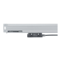
Describes the universal measuring adapter for testing connector inputs/outputs.
Introduces the encoder diagnostic set for testing encoder electrical functions.
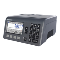
Introduces the Drive Control Generator (DCG) and its specifications.
Lists important notes and safety instructions before starting component exchange.
Lists the necessary equipment for component exchange.
Explains the necessity and procedure for MOS protection during EPROM exchange.
Discusses software compatibility for exchange units and boards.
Details the procedure for exchanging NC software, including backup and status setup.
Explains how RAM data is backed up and restored during software exchange.
Describes how to prepare the machine and axes before software exchange.
Explains how to convert hard disk data from binary to ASCII format.
Provides instructions and location diagrams for exchanging EPROMs.
Details steps for putting the control into service after software or hardware changes.
Explains how to convert hard disk data from ASCII back to binary format.
Guides on installing system data from a setup disk onto the hard disk.
Describes procedures to restore the machine tool to its original state after exchange.
Outlines preparations at the machine tool before exchanging the logic unit.
Provides crucial information regarding hard disk data when exchanging the logic unit.
Details the steps for safely dismounting the logic unit.
Describes the procedure for mounting the logic unit.
| Control Type | CNC |
|---|---|
| Power Supply | 24 V DC |
| Operating Temperature | 0 to 45 °C |
| Storage Temperature | -20 to 70 °C |
| Programming | ISO |
| Display | LCD |
| Interface | RS-232 |
| Humidity | Max. 95% relative humidity, non-condensing |