21
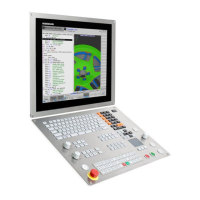
Of course the TNC 640 also shows the
machine operator—both with an error
message and graphically—which machine
components are endangered. If a collision
warning is displayed, the TNC permits
retracting the tool only in those directions
which increase the clearance between the
colliding objects.
The machine tool builder takes care of the
required definition of machine compo-
nents. The working space and the collision
objects are described using geometric
bodies such as planes, cubes and cylinders.
Complex machine components can be
modeled with multiple geometric bodies.
The tool is automatically considered a
cylinder of the tool radius (defined in the
tool table). For tilting devices, the machine
tool builder can use the description of the
machine kinematics also to define the
collision objects.
The last step of the configuration process
defines which machine components can
collide. Because the machine design in
itself prevents collisions between certain
machine components, they can be ruled
out from the start. For example, a tool
touch probe like the HEIDENHAIN TT
clamped on the machine table can never
collide with the machine cabin.
When using the dynamic collision
monitoring, please note:
• DCM can help to reduce the danger of
collision. However, DCM cannot
completely prevent collisions.
• Only the machine manufacturer can
define machine components.
• Collisions between machine
components (such as swivel heads) and
the workpiece cannot be detected.
• DCM cannot be used during operation in
following error mode (which means
without feedforward).

 Loading...