Do you have a question about the HEIDENHAIN MANUALPLUS 4110 and is the answer not in the manual?
Overview of the MANUALplus 4110 user training manual.
Covers foundational concepts of the MANUALplus 4110 system.
Details on the various components the user interacts with.
Introduction to the fundamental operations of the system.
Covers the management and organization of tools.
Explains how to measure and set tool parameters.
Guides on setting up the machine for operation.
Step-by-step example of longitudinal machining.
Step-by-step example of surface machining.
Step-by-step example of recess machining.
Explains how to use the simulation features.
Instructions on how to execute programs.
Explains the X and Z axis conventions and movements.
Details on using positive and negative values for axis movement.
Defines machine datum (M) and workpiece datum (W).
Discusses implications of tool being in front or behind workpiece.
Defines X/Z coordinates for tool tip and contour elements.
Explains how C axis angles are referenced to the datum.
Specifies the precision for programming and displaying positions.
Paths referenced to the theoretical tool tip (S).
Removes inaccuracies caused by tool tip radius.
Methods include feed rate per revolution and per minute.
Options for constant spindle speed or constant cutting speed.
Explains how maximum speed affects programmed speeds.
Explains Menu and Process keys for navigation and mode selection.
Describes Backspace, Switching, and Clear keys for editing.
Covers keys for entering numbers, decimal points, and signs.
Explains Enter and Store keys for input confirmation.
Details Arrow and Page forward/back keys for navigation.
The Info key displays error or PLC status information.
Explains how menu fields correspond to keypad numbers.
Describes soft keys located at the bottom of the screen.
Explains soft keys that switch between states.
Shows X, Z, and C axis current position values.
Explains colors indicating active or inactive axes.
Displays remaining distance for traversing commands.
Specific details for distance-to-go display during manual operations.
Symbols indicating the status of protection zone monitoring.
Details programmed, overridden, and actual feed rates.
Defines feed rate per revolution (mm/r) and per minute (mm/min).
Shows programmed speed, override, actual speed, and gear range.
Displays target and current spindle position.
Identifies displays related to driven tools.
Procedures for setting constant cutting speed or spindle speed.
Displays relative motor performance and speed limitation.
Shows the identification letter 'T' for tools.
T number indicates position in tool management.
Includes tool position and rotated turret position.
Step-by-step guide for switching on the machine.
Conditions required for axes and spindle to be enabled.
Color coding for enabled (black) vs. disabled (white) axes.
Steps for performing a reference run on axes.
Sequence for standard and distance-coded encoders.
The system assumes the most recently active tool is in the holder.
Step-by-step guide to switch between operating modes.
Procedures for deleting errors via Backspace or Clear keys.
Steps to address PLC status messages.
Navigating between error windows and PLC status displays.
Highlights the need for proper shutdown to prevent data loss.
Contains geometric data and cutting values for tool identification.
Explains how to measure and enter setup dimensions for tools.
Steps to activate Tool Management mode and add a tool.
Inputting setup dimensions, angles, and compensation values.
Adding descriptive text for better tool identification.
Inputting machining direction, cutting speed, and feed rate.
Provides a complete overview of the entered data for Tool T1.
Explains how copying reduces data entry time and effort.
Steps to load T1 data and specify T2 position.
Modifying parameters like tip angle after copying.
Provides a complete overview of the entered data for Tool T2.
Steps to copy existing tool data to position T6.
Modifying cutting radius and entering tool description.
Adding descriptive text for tool T6.
Inputting machining direction, cutting speed, and feed rate for T6.
Provides a complete overview of the entered data for Tool T6.
Steps to set up the threading tool T8 in the manager.
Inputting basic parameters for the threading tool.
Adding descriptive text for the threading tool T8.
Inputting machining direction and shaft speed for T8.
Provides a complete overview of the entered data for Tool T8.
Steps to set up the recessing tool T10 in the manager.
Inputting basic parameters for the recessing tool.
Adding descriptive text for the recessing tool T10.
Inputting machining direction and cutting speed for T10.
Provides a complete overview of the entered data for Tool T10.
Explains the process of determining tool dimensions.
Includes clamping the workpiece and tool T1.
Navigating to the 'Set S, F, and T' menu.
Loading tool data, including T1, from the tool file.
Loads cutting speed and feed rate from the tool file.
Confirms T1 using the tool-change key.
Sets the workpiece datum by positioning the tool.
Uses the Z=0 soft key to define the faced surface as datum.
Determining exact setting dimensions for tool T1.
Accessing the function to measure the tool's dimensions.
Turning the workpiece to create a diameter for measurement.
Inputting the measured diameter into the X coordinate.
Determining X and Z dimensions for tool T2.
Loading tool T2 into the system for measurement.
Shows loaded parameters for tool T2.
Confirms T2 selection after loading.
Measures the workpiece diameter using tool T2.
Measures the end face to set the Z datum with tool T2.
Determining X and Z dimensions for tool T6.
Loading tool T6 into the system for measurement.
Shows loaded parameters for tool T6.
Measures the workpiece diameter using tool T6.
Measures the end face to set the Z datum with tool T6.
Determining X and Z dimensions for tool T8.
Loading tool T8 into the system for measurement.
Shows loaded parameters for tool T8.
Measures the workpiece diameter using tool T8.
Measures the end face to set the Z datum with tool T8.
Determining X and Z dimensions for tool T10.
Loading tool T10 into the system for measurement.
Shows loaded parameters for tool T10.
Measures the workpiece diameter using tool T10.
Measures the end face to set the Z datum with tool T10.
Functions include tool activation, data entry, and point definition.
Includes clamping the workpiece and tool T1.
Navigating to the 'Set S, F, and T' menu for data input.
Assumes data from the tool file for tool T1.
Verifies T1 selection after loading data.
Step-by-step process to set the workpiece datum.
Uses the Z=0 soft key to define the faced surface as the workpiece datum.
Steps to define the protection zone for safe operation.
Moves the tool tip to the desired protection zone position.
Visual indicators for protection zone monitoring status.
Steps to define the position for automatic tool changes.
Positions the tool for the tool change operation.
Introduces the example program for creating a threaded stud.
Lists necessary conditions before starting program creation.
Enters the mode for creating new cycles.
Steps to name and list a new cycle program.
Defines the workpiece blank type and dimensions.
Inputting values like diameter, length, and clamping range.
Creates the main ICP cycle for longitudinal cutting.
Inputting parameters like starting point, speed, and feed rate.
Loads tool number, speed, and feed rate from the tool file.
Defines the contour description and machining direction.
Opens the ICP editor to create contour elements.
Defines the first contour element as a chamfer.
Defines the second contour element as a thread undercut.
Defines the third contour element as an oblique cut.
Defines the fourth contour element as a horizontal line.
Defines the fifth contour element as a rounding (radius).
Defines the sixth contour element as a vertical line.
Defines the seventh contour element as a chamfer.
Defines the eighth contour element as a horizontal line.
Defines the ninth contour element as a vertical line.
Assigns a name to the created ICP contour.
Takes over the entered contour name into the list.
Finishes and verifies the roughing cycle, handling warnings.
Addresses warnings that may occur during cycle execution.
Executes the roughing machining pass.
Sets up the cycle for approaching the tool change position.
Executes the programmed cycle to change tools.
Copies an existing ICP cycle to create the finishing cycle.
Modifies parameters for the finishing cycle.
Simulates the finishing pass to check tool path and geometry.
Executes the finishing machining pass.
Accesses the tool compensation function.
Applies compensation values based on measurement.
Re-runs the finishing cycle after compensation.
Creates the dedicated cycle for thread cutting.
Loads necessary tool and technology data for threading.
Simulates the threading process for verification.
Addresses any warnings displayed during simulation.
Executes the actual threading operation.
Applies compensation to the threading tool.
Re-runs the last thread cut after applying compensation.
Sets up tool change approach for the threading tool.
Shows the finished workpiece, program, and contour.
Introduces the example program for transverse machining.
Lists necessary conditions before starting the Matrix program.
Steps to start creating a new cycle for the Matrix example.
Configures the workpiece blank parameters for the Matrix cycle.
Creates the ICP cycle for transverse machining.
Executes and simulates the Matrix cycle program.
Sets up the tool change approach cycle for the Matrix program.
Creates the finishing cycle for the Matrix example.
Simulates the finishing pass of the Matrix cycle.
Executes the finishing pass of the Matrix cycle.
Sets up the tool change approach for the Matrix finishing cycle.
Shows the finished workpiece and program details.
Guidelines for creating the contour.
Accesses the ICP editor and contour list.
Defines the first contour segment as a vertical line.
Defines the second contour segment as a horizontal line.
Defines the third contour segment as an oblique cut.
Defines the fourth contour segment as an arc.
Defines the fifth contour segment as an oblique cut.
Adds the first rounding to the contour.
Adds the second rounding to the contour.
Adds the third rounding to the contour.
Assigns the name 'Matrix' to the ICP contour.
Defines the contour for finishing operations.
Copies an existing contour for the finishing process.
Renames the copied contour to 'Matrix – finishing contour'.
Introduces the example program for recessing machining.
Lists necessary conditions before starting the Form Roll program.
Steps to start creating a new cycle for the Form Roll example.
Configures the workpiece blank parameters for the Form Roll cycle.
Creates the ICP cycle for radial cutting.
Inputting parameters like starting point, speed, and feed rate.
Simulates the Form Roll cycle to check the tool path.
Verifies the cycle execution and displays subsequent paths.
Executes the Form Roll machining cycle.
Copies the ICP radial cycle for finishing.
Modifies parameters for the finishing pass.
Simulates the finishing pass of the Form Roll cycle.
Executes the finishing pass of the Form Roll cycle.
Shows the finished workpiece and program details.
Guidelines for creating the contour.
Accesses the ICP editor and contour list.
Defines the first contour segment as a horizontal line.
Defines the second contour segment as an arc.
Defines the third contour segment as an oblique cut.
Defines the fourth contour segment as an oblique cut.
Defines the fifth contour segment as a horizontal line.
Defines the sixth contour segment as an oblique cut.
Defines the seventh contour segment as a horizontal line.
Adds the first rounding to the contour.
Adds the second rounding to the contour.
Adds the third rounding to the contour.
Assigns the name 'Form Roll' to the ICP contour.
Describes wire frame, cutting path, and machining simulation views.
Displays traverse paths as lines without cutter geometry.
Shows cutter geometry and checks for material remaining.
Displays the blank as a white surface being machined.
Allows showing or hiding the tool tip in graphics.
Opens the 'Extra functions' menu for simulation settings.
Switches between cutting path (Track) and cutter graphics (Slide).
Activates the machining simulation view.
Isolates and magnifies specific areas of the simulation display.
Adjusts the displayed simulation area (reduce, increase, move).
Decreases the size of the workpiece display to select a section.
Steps to take before running a program: load, check, simulate.
Enters the mode for executing stored programs.
Chooses and loads a program from the program list.
Displays and clears warnings or errors detected during program load.
Verifies cycle parameters by placing cursor on the cycle.
Simulates the program execution graphically.
Lists all conditions that must be met before running a program.
Executes cycles one by one when 'Continuous run' is off.
Executes the entire cycle program, handling tool changes.
Compensation values can be applied during or saved with program execution.
Stops program run after finishing cycle to measure workpiece.
Measures the workpiece diameter after the finishing cycle.
Inputs the measured compensation value into the DX field.
Re-runs the finishing cycle after applying tool compensation.
| Brand | HEIDENHAIN |
|---|---|
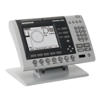
| Model | MANUALPLUS 4110 |
| Category | Control Panel |
| Language | English |