HEIDENHAIN MANUALplus 4110 System Operation 3.4
Machine data display
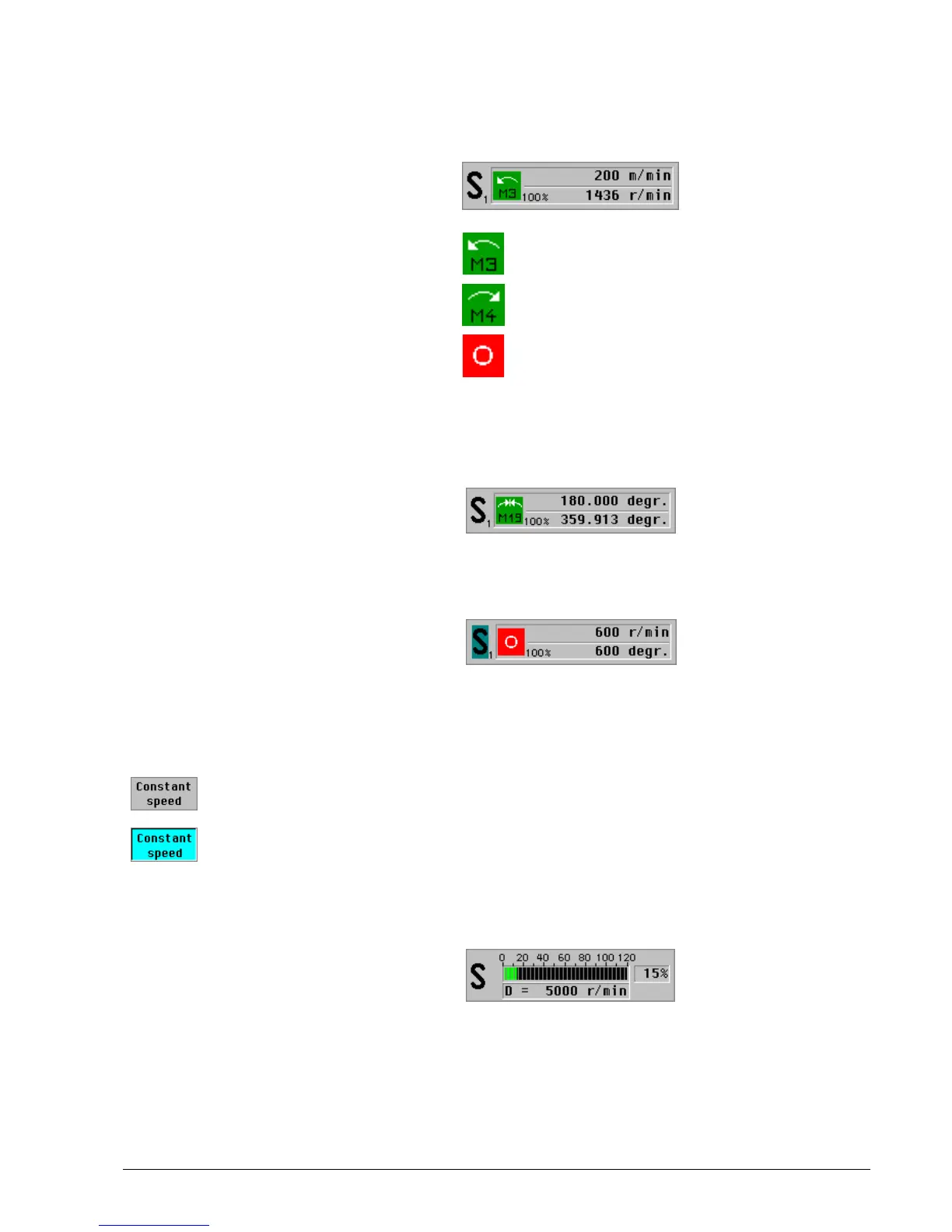
Spindle display
Setting the cutting speed or spindle speed:
Spindle utilization
Spindle display element:
Top line: Programmed cutting speed
or spindle speed
Bottom line:
Current speed override
Actual spindle speed (taking the
speed override into account)
Little number beside the S: Gear range
Units:
Cutting speed: m/min
Spindle speed: r/min
Spindle rotates counterclockwise (M3)
Spindle rotates clockwise (M4)
Spindle stop
Display for positioning of spindle
(M19):
Top line: Target position
Bottom line: Current position
Driven tool:
Identification: The S is highlighted
The display refers to the driven tool
Set a constant cutting speed (the constant spindle speed is deactivated)
Set a constant spindle speed
Spindle utilization display element:
Current performance of the spindle
motor relative to the rated motor
performance
Bottom line: Maximum speed (speed
limitation)

 Loading...