31
Programming graphics
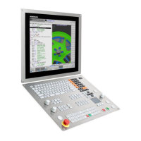
The two-dimensional programming
graphics give you additional security: while
you are programming, the TNC 640 draws
every entered traverse command on the
screen.
Help graphics
During cycle programming in the plain-
language dialog, the TNC shows a separate
illustration for each parameter. This makes
it easier to understand the function and
accelerates programming. The TNC 640
also supports you with useful help graphics
when programming the PLANE function
and the contour elements for turning.
– Graphic support in any situation
Program verification graphics
To be on the safe side before running a
program, the TNC can graphically simulate
the machining progress. The new finely
detailed 3-D test graphics enables you to
evaluate exactly the manufactured result
even before the actual machining. You
define the workpiece blank as a cuboid,
cylinder or rotationally symmetric part with
any contour. The TNC offers various ways to
depict machining:
• Plan view with different shades of depth
• Three planes (as in the workpiece
drawing)
• High-resolution 3-D view
• 3-D line graphics of the tool paths
You can adjust the type and quality of the
image. Details can be displayed in
magnification. In addition, the TNC
indicates the calculated machining time in
hours, minutes and seconds.
Program-run graphics
On the TNC 640, you can run the program-
run graphics or verification graphics even
while the workpiece is being machined.
Also, it shows a real-time graphic of the
milling progress during program run.
Coolant spray and protective enclosures
usually obstruct any direct view of the
actual workpiece. You can get around this
with a simple keystroke to see the simulated
progress of workpiece milling.
3-D line graphics
The 3-D line graphics display the pro-
grammed tool center point path in three
dimensions. With the powerful zoom
function you can also see the finest details.
You should especially use the 3-D line
graphics to inspect programs created
offline for irregularities before machining, in
order to avoid undesirable traces of the
machining process on the workpiece, e.g.
when points are output incorrectly by the
postprocessor.

 Loading...