INSTALLATION INSTRUCTIONS Fan Coils: FEM4X, FEM4P, REM4X
10 496 01 5503 00
Specifications are subject to change without notice.
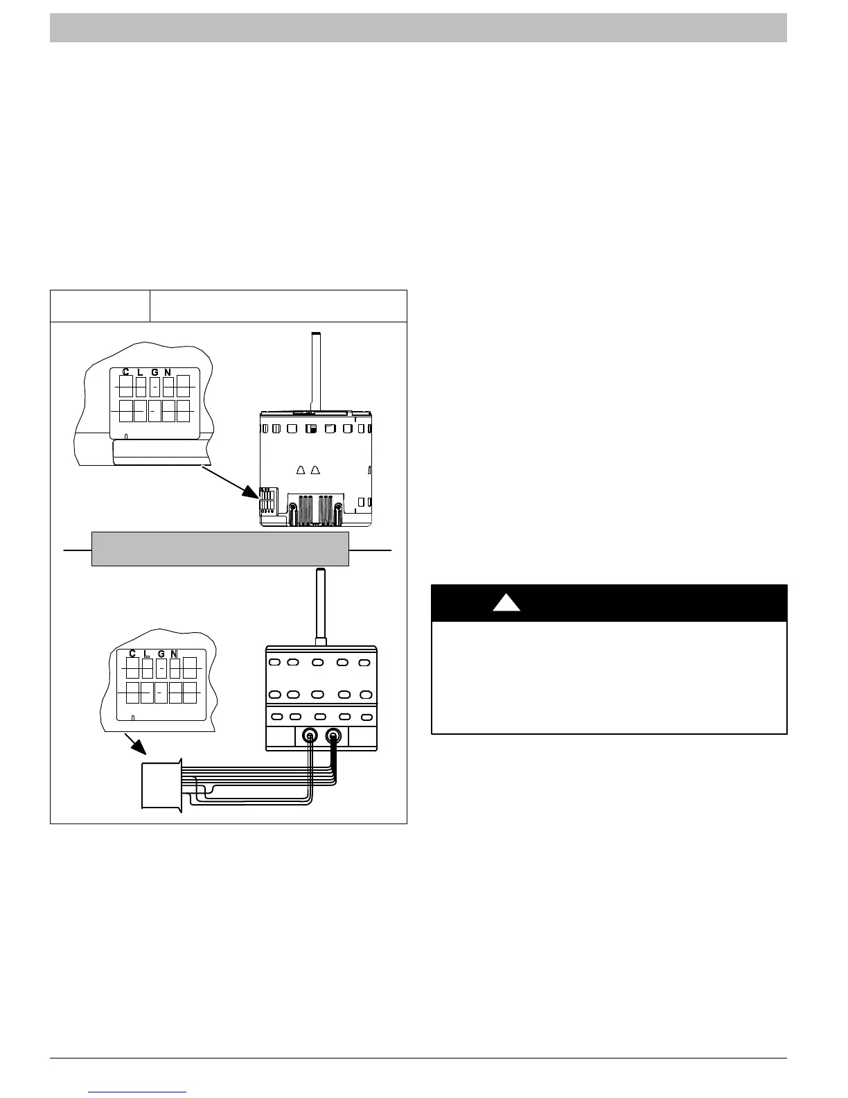
To change motor speeds disconnect the BLUE fan lead from
motor connector terminal #2 (factory default position) and
move to desired speed tap; 1, 2, 3, or 5 (see Figure 15).
Speed taps 1, 2, and 3 have a 90 second blower off time
delay pre−programmed into the motor. Speed tap 4 is used
for electric heat only (with 0 second blower time delay) and
the WHITE wire should remain on tap 4. Speed tap 5 is used
for high static applications, but has a 0 second blower time
delay pre−programmed into the motor (see Airflow
Performance Tables for actual CFM for each tap). Also, see
Figure 15 for motor speed selection location.
NOTE: In low static applications, lower motor speed tap
should be used to reduce possibility of water being blown off
coil.
Figure 15
FEM4X, FEM4P, REM4X
Motor Speed Selection
1 2 3 4 5
Speed Taps may be located on motor,
or on plug close to motor.
L11S018
CLGN
1 2 3 4 5
REFRIGERANT TUBING
Refrigerant Tubing Connection and Evacuation
Use accessory tubing package or field−supplied tubing of
refrigerant grade. Suction tube must be insulated. Do not
use damaged, dirty, or contaminated tubing because it may
plug refrigerant flow−control device. ALWAYS evacuate the
coil and field−supplied tubing to 500 microns before opening
outdoor unit service valves.
Units have sweat suction and liquid tube connections. Make
suction tube connection first.
1. Cut tubing to correct length.
2. Insert tube into sweat connection on unit until it
bottoms.
3. Braze connection using silver bearing or non−silver
bearing brazing materials. Do not use solder
(materials which melt below 800_F / 427_C). Consult
local code requirements.
4. Evacuate coil and tubing system to 500 microns using
deep vacuum method.
Size and install refrigerant lines according to information
provided with outdoor unit. Route refrigerant lines to the fan
coil in a manner that will not obstruct service access to the
unit or removal of the filter.
1. Find the liquid tube grommet in the small−parts bag
and slide it onto the liquid refrigerant line (field
line−set).
2. Remove the lower door. Remove the tubing plate (with
suction tube grommet) and slide the plate with
grommet onto the refrigerant lines (field line−set),
away from braze joints.
3. Remove rubber plugs from coil stubs using a pulling
and twisting motion. Hold coil stubs steady to avoid
bending or distorting.
4. Wrap TXV and nearby tubing with a heat−sinking
material such as a wet cloth.
5. Fit refrigerant lines into coil stubs. Wrap a heat sinking
material such as a wet cloth behind braze joints.
6. Braze using a Sil−Fos or Phos−copper alloy.
7. After brazing, allow joints to cool. Slide tubing plate
back into place and position grommets around suction
and liquid tubes to ensure air seal.
PRODUCT DAMAGE HAZARD
Failure to follow this caution may result in product or
property damage.
Wrap a wet cloth around rear of fitting to prevent
damage to piston assembly or TXV and
factory−made joints.
CAUTION
!
REFRIGERANT FLOW−CONTROL
DEVICE
FEM4P Models:
These units come equipped with a factory installed Piston
metering device with Teflon ring
. If a piston replacement REs
required, check piston size shown on indoor unit rating plate
to see if it matches required outdoor piston size. The outdoor
piston size will be found on the outdoor unit rating plate,
product data or installation instructions depending on the
model shown on outdoor unit rating plate. If the fan coil
piston does not match, replace indoor piston with correct
outdoor piston. With some outdoor units a piston is shipped
with outdoor unit.
When changing piston, use a back−up wrench. Hand tighten
hex nut, then tighten with wrench 1/2 turn. Do not exceed 30
ft−lbs.
NOTE: The indoor piston contains a Teflon ring (or seal)
which is used to seat against the inside of distributor body,
 Loading...