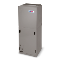
INSTALLATION INSTRUCTIONS Fan Coils: FEM4X, FEM4P, REM4X
496 01 5503 00 7
Specifications are subject to change without notice.
E. MANUFACTURED HOUSING AND MOBILE HOME
APPLICATIONS
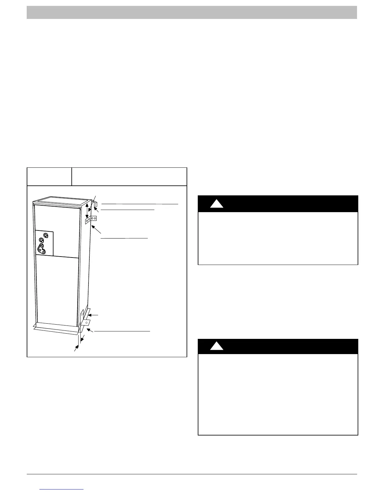
1. Fan coil unit must be secured to the structure using
field−supplied hardware.
2. Allow a minimum of 24 inches (610mm) clearance
from access panels.
3. Recommended method of securing for typical
applications:
a. If fan coil is away from wall, attach pipe strap to top
of fan coil using No. 10 self tapping screws. Angle
strap down and away from back of fan coil, remove
all slack, and fasten to wall stud of structure using
5/16” lag screws. Typical both sides of fan coil.
b. If fan coil is against wall, secure fan coil to wall stud
using 1/8” (3mm) wide right−angle brackets. Attach
brackets to fan coil using No. 10 self tapping screws
and to wall stud using 5/16” lag screws (refer to
Figure 7).
Figure 7
Mobile Home or Manufactured
Housing Applications
(TYPICAL BOTH SIDES)
OR
DOWN FLOW
BASE KIT
UNIT AGAINST WALL
1/8” (3mm) INCH THICK ANGLE
MOUNTING BRACKET
(TYPICAL BOTH SIDES)
SECURE FAN COIL TO STRUCTURE
UNIT AWAY FROM WALL
PIPE STRAP
SECURE UNIT TO FLOOR
ANGLE BRACKET OR PIPE STRAP
4” (102mm) MAX
4” (102mm) MAX
AIR DUCTS
Connect supply−air duct over the outside of 3/4” flanges
provided on supply−air opening. Secure duct to flange using
proper fasteners for type of duct used, and seal duct−to−unit
joint.
It is a recommendation, but not a requirement, to use flexible
connections between ductwork and unit to prevent
transmission of vibration. When electric heater is installed,
use heat−resistant material for flexible connector between
duct work and unit at discharge connection. Duct work
passing through unconditioned space must be insulated and
covered with vapor barrier.
Duct Work Acoustical Treatment
Metal duct systems that do not have a 90 degree elbow and
10 feet of main duct before first branch takeoff may require
internal acoustical insulation lining. As an alternative,
fibrous duct work may be used if constructed and installed in
accordance with the latest edition of SMACNA construction
standard on fibrous glass ducts. Both acoustical lining and
fibrous duct work shall comply with National Fire Protection
Association as tested by UL Standard 181 for Class 1 air
ducts.
ELECTRICAL CONNECTIONS
FEM4X, FEM4P, and REM4X Fan Coil models do not have a
printed circuit board (PCB), they have a low voltage circuit
protective fuse (3 amp) inline on the wire harness. Speed
selections are made at the fan motor with the Blue wire. The
motor is pre−programmed with the time−delay circuit on some
of the speed taps. (See Page 9, Section D)
Before proceeding with electrical connections, make certain
that supply voltage, frequency, phase, and circuit ampacity are
as specified on the unit rating plate. See unit wiring label for
proper field high and low voltage wiring.
!
WARNING
ELECTRICAL SHOCK or UNIT DAMAGE HAZARD
Failure to follow this warning could result in personal
injury, death, and/or unit damage.
If a disconnect switch is to be mounted on unit, select a
location where drill and fasteners will not contact
electrical or refrigeration components.
Make all electrical connections in accordance with the NEC
and any local codes or ordinances that may apply. Use
copper wire only. The unit must have a separate branch
electric circuit with a field−supplied disconnect switch
located within sight of and readily accessible from the unit.
NOTE: When a pull−out type disconnect is removed from
the unit, only the Load side of the circuit is de−energized.
The Line side remains live until the main (remote)
disconnect is turned off.
!
WARNING
ELECTRICAL SHOCK HAZARD
Failure to follow this warning could result in personal
injury or death.
Turn off the main (remote) disconnect device before
working on incoming (field) wiring.
Incoming (field) wires on the line side of the disconnect
found in the fan coil unit remain live, even when the
pull−out is removed. Service and maintenance to
incoming (field) wiring cannot be performed until the main
disconnect switch (remote to the unit) is turned off.
 Loading...