INSTALLATION INSTRUCTIONS Fan Coils: FEM4X, FEM4P, REM4X, FXM4X
496 01 5503 02 3
Specifications are subject to change without notice.
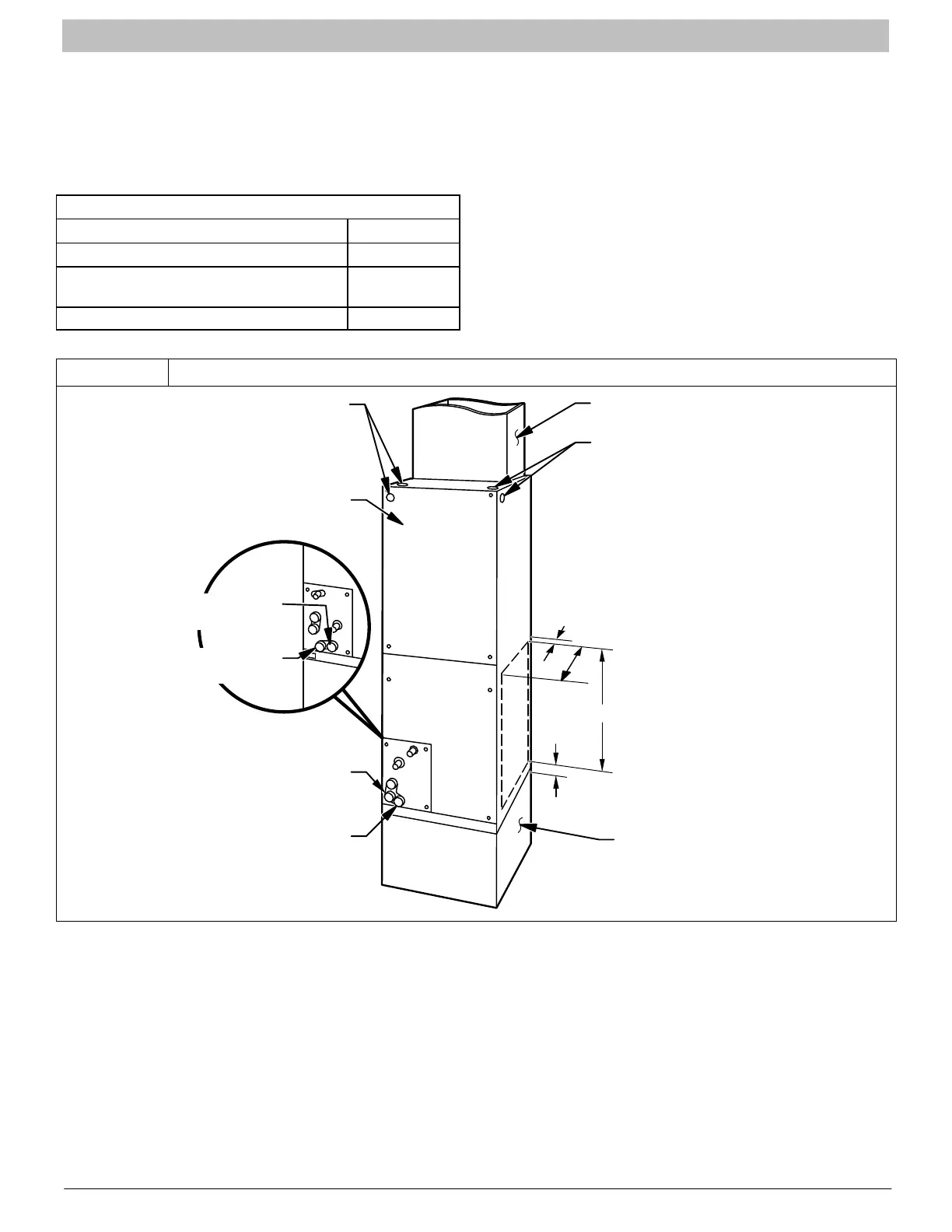
A. UPFLOW INSTALLATION
If return air is to be ducted through a floor, set unit on floor
over opening and use 1/8 to 1/4 inch thick (3 to 6 mm thick)
fireproof resilient gasket between duct, unit, and floor.
Side return is a field option on slope coil models. Cut opening
per dimensions shown in Figure 2. A field−supplied bottom
closure is required.
SLOPE COIL UNITS
MODEL A
FEM18, REM18 12” (305mm)
FXM18, FEM24, FXM24, REM24,
FEM30, REM30, FEM36, REM36
17” (432mm)
FXM30 19” (483mm)
B. MODULAR UNITS
FEM4X6000B, REM4X6000B, and FXM4X4800/6000 fan
coils are two−piece modular units. This allows for modular
units to be disassembled and components moved separately
to installation area for reassembly. This process
accommodates small scuttle holes and limiting entrances to
installation sites (Figure 1).
Figure 2 Upflow Installation
FRONT SERVICE CLEARANCE
18 − 48 models = 21” (533 mm)
60 model = 24” (610 mm)
A−COIL
UNITS
POWER ENTRY
OPTIONS
LOW VOLT
ENTRY
OPTIONS
FIELD MODIFIED
SIDE RETURN
LOCATION FOR
SLOPE COIL
UNITS ONLY
FIELD SUPPLIED
RETURN PLENUM
UPFLOW/DOWNFLOW
SECONDARY DRAIN
UPFLOW/DOWNFLOW
PRIMARY DRAIN
A
FIELD SUPPLIED
SUPPLY DUCT
UPFLOW/DOWNFLOW
SECONDARY DRAIN
UPFLOW/DOWNFLOW
PRIMARY DRAIN
1½”
2½”
(64mm)
19” (483mm)