INSTALLATION INSTRUCTIONS Fan Coils: FEM4X, FEM4P, REM4X, FXM4X
496 01 5503 02 11
Specifications are subject to change without notice.
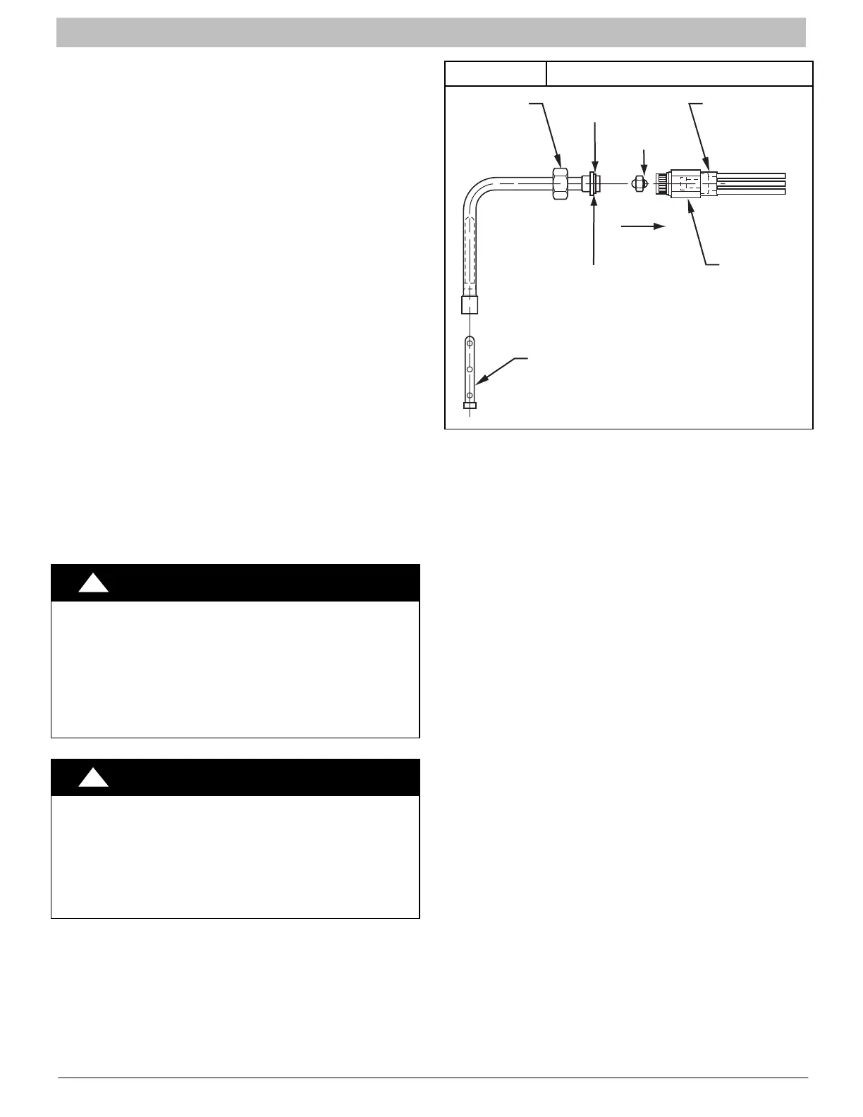
REFRIGERANT FLOW−CONTROL DE-
VICE
FEM4P Models:
These units come equipped with a factory installed Piston
metering device with Teflon ring
. If a piston replacement is
required, check piston size shown on indoor unit rating plate
to see if it matches required outdoor piston size. The outdoor
piston size will be found on the outdoor unit rating plate,
product data or installation instructions depending on the
model shown on outdoor unit rating plate. If the fan coil piston
does not match, replace indoor piston with correct outdoor
piston. With some outdoor units a piston is shipped with
outdoor unit.
When changing piston, use a back−up wrench. Hand tighten
hex nut, then tighten with wrench 1/2 turn. Do not exceed 30
ft−lbs.
NOTE: The indoor piston contains a Teflon ring (or seal)
which is used to seat against the inside of distributor body,
and must be installed properly to ensure proper seating in the
direction for cooling operation.
Always use outdoor units designed to match indoor fan coil
applications.
REFRIGERANT METERING DEVICE
FEM4X, REM4X, FXM4X Models:
These Fan Coils have a factory installed hard shut−off TXV
designed only for use with R−410A refrigerant. Use only with
outdoor units designed for R−410A.
TXV is factory set and not field adjustable.
!
CAUTION
PRODUCT DAMAGE HAZARD
Failure to follow this caution may result in product
damage.
This Fan Coil has a hard shut−off TXV metering device. A
compressor Hard Start Kit is REQUIRED in all
applications where the matching outdoor unit has a
single−phase reciprocating compressor.
!
CAUTION
PRODUCT OPERATION HAZARD
Failure to follow this caution may result in improper prod-
uct operation.
If using a TXV in conjunction with a single−phase recipro-
cating compressor, a compressor start capacitor and relay
are required. Consult outdoor unit pre−sale literature for
start assist kit part number.
Figure 15 Refrigerant Flow−Control Device
TEFLON SEAL
BRASS
HEX NUT
STRAINER
PISTON
RETAINER
BRASS
HEX BODY
DISTRIBUTOR
PISTON
FLOW IN
COOLING
TEFLON RING
CONDENSATE DRAINS
Unit is provided with primary and secondary 3/4” (19mm)
NPT drain connections. Refer to Figure 2, Figure 3,
Figure 4, Figure 5, and Figure 6 to identify the primary and
secondary locations. To prevent property damage and
achieve optimum drainage performance, BOTH primary and
secondary drain lines should be installed and include
properly sized condensate traps (refer to Figure 16).
Factory approved condensate traps are available (accessory
part number EBAC01CTK).
To connect drainlines, the drain connection knock−outs must
be removed. Use a knife to start the opening near the tab and
using pliers, pull the tab to remove the knock−out. Clean the
edge of the opening if necessary. After drain fittings are
installed, caulk the seam between the fitting and the cover to
retain the low leak rating of the unit.
It is recommended the PVC fittings be used on the plastic
condensate pan. Do not over−tighten. Finger−tighten plus
1−1/2 turns. Use pipe dope to ensure proper seal.
Install traps in the condensate lines as close to the coil as
possible (refer to Figure 18), but avoid blocking filter access
panel.
Install drain lines below the bottom of the drain pan and pitch
the drain lines down from the coil at least 1/4 inch per foot of
run (6mm per 0.3m). Horizontal runs over 15 feet (5m) long
must also have an anti−siphon air vents (stand pipes),
installed ahead of the horizontal runs. Extremely long
horizontal runs may require oversized drain lines to eliminate
air trapping.
Route primary drain line to the outside or to a floor drain.
Check local codes before connecting to a waste (sewer) line.
Route the secondary drain line to a place in compliance with
local installation codes where it will be noticed when unit is
operational. Condensate flowing from secondary (overflow)
drain indicates a plugged primary drain − unit requires
service or water damage will occur.