INSTALLATION INSTRUCTIONS R-410A, Two-Stage Split System Air Conditioner
421 01 6001 00 11
TROUBLESHOOTING
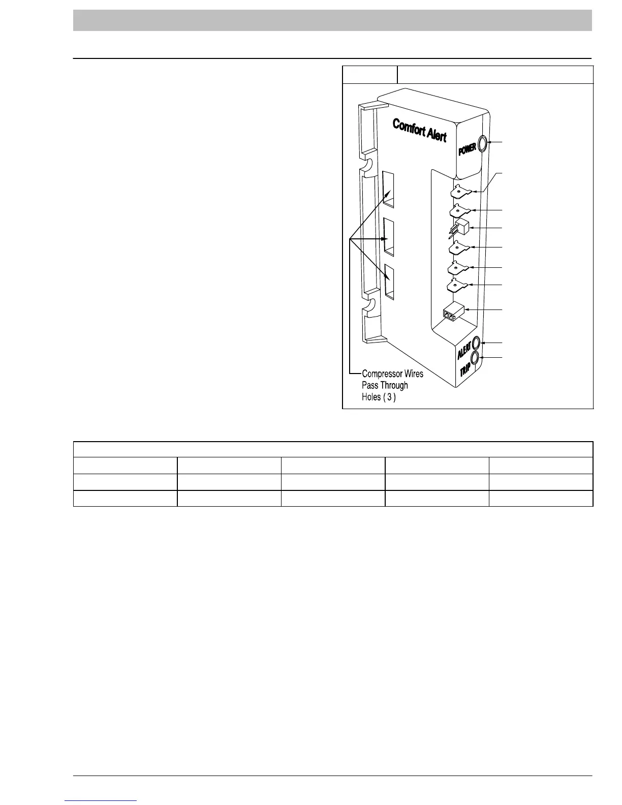
Models are factory equipped with the Comfort Alert
UltraTech Diagnostics device (refer to Figure 11) in the
control box. Comfort Alert UltraTech provides
compressor staging from low to high and high to low
capacity. Comfort Alert UltraTech provides
around-the-clock monitoring for common electrical
problems, compressor defects, and broad system faults.
If trouble is detected, an alert code is displayed with a
flashing LED indicator. Alert codes are listed in Figure 12.
The device is factory wired and requires no
modification. Low voltage lead wires are provided in the
control box for connection to thermostat wires (use wire
nuts).
The Comfort Alert UltraTech must be powered to properly
stage compressor to high capacity. Energizing the Y (Y1)
terminal operates the compressor in low stage. Both the
Y (Y1) and Y2 terminals must be energized for
high-stage operation.
The Comfort Alert UltraTech device operates by
monitoring the compressor power leads and the
thermostat demand signals Y (Y1) and Y2 terminals. It
draws constant 24 VAC power at the R and C terminals.
When the compressor is operating in low stage (Y or Y1),
the 24v DC compressor solenoid coil is de-energized.
When the compressor is operating in high stage (Y or Y1
and Y2), the 24v DC solenoid coil is energized. The 24v
DC plug that is connected to the compressor does NOT
have an internal rectifier. DO NOT INSTALL A PLUG
WITH INTERNAL RECTIFIER.
Figure 11
Comfort Alertt UltraTecht Diagnostics
Y2
Y
L
R
C
R
C
S
“Power” LED
Thermostat Demand
1
st
Stage Compressor
Data Port
Thermostat Signal
24 VAC HOT
24 VAC Common
DC Compressor
Solenoid
“Alert” LED
“Trip” LED
Thermostat Demand
2
nd
Stage Compressor
Two-Stage Compressor Resistance (winding resistance) at 70°F +/- 20°F
Winding *4A624 *4A836 *4A648 *4A660
Start (S-C) 1.40 1.29 1.52 0.60
Run (R-C) 1.32 0.89 0.64 0.49
NOTE: The rectifier for the DC solenoid is contained
within the Comfort Alert UltraTech device. The plug at the
compressor solenoid is an ordinary 2-wire plug. Never
use a plug with internal rectifier with this system.
NOTE: The DC compressor solenoid plug that connects
to the Comfort Alert UltraTech is polar dependent and
should only be connected with the tabs aligned.
Unloader Test Procedure with Comfort Alertt Module
The unloader is the compressor internal mechanism,
controlled by the DC solenoid, that modulates between
high and low stage.
If it is suspected that the unloader is not working, the
following methods may be used to verify operation.
1. Operate the system and measure compressor
amperage. Cycle the unloader on and off at ten
plus second intervals by applying and removing Y2
voltage to the module. Wait five seconds after
power is applied to Y2 before taking a reading. The
compressor amperage should go up or down at
least 25 percent.
2. If step one does not give the expected results,
remove the solenoid plug from the compressor
and, with the unit running and the thermostat
calling for Y2 to be energized, test the voltage
output at the plug with a DC voltmeter.
The reading here should be 4 to 18 volts. If NOT,
unplug the harness from the module and check
voltage at the “DC Sol” pins of the module. The
module will not power the unloader solenoid if the
compressor is not running or fault code 1 or 9 is
active.
3. If the correct DC voltage is at the control circuit
molded plug, measure the unloader coil
resistance. The resistance should be 32 to 60
ohms depending on compressor temperature. If
the coil resistance is infinity, much lower than 32
ohms, or is grounded, the compressor must be
replaced.