INSTALLATION INSTRUCTIONS R-410A, Two-Stage Split System Air Conditioner
8 421 01 6001 00
ELECTRICAL WIRING
!
WARNING
ELECTRICAL SHOCK HAZARD
Failure to follow this warning could result in per‐
sonal injury or death.
Before installing, modifying or servicing system,
turn OFF the main (remote) electrical disconnect
device. There may be more than one disconnect
device.
The supply voltage must be 208/230 volts (197 volt
minimum to 253 volts maximum) 60 Hz single phase.
Outdoor units are approved for use with copper
conductors only. Do not use aluminum wire.
Refer to unit rating plate for minimum circuit ampacity and
circuit protection requirements.
Grounding
Permanently ground unit in accordance with the National
Electrical Code and local codes or ordinances. Use a
copper conductor of the correct size from the grounding
lug in control box to a grounded connection in the service
panel or a properly driven and electrically grounded
ground rod.
Wiring Connections
Make all outdoor electrical supply (Line Voltage)
connections with raintight conduit and fittings. Most
codes require a disconnect switch outdoors within sight of
the unit. Consult local codes for special requirements.
Route electrical supply (Line Voltage) wiring through
knockout hole in bottom of Control Box. Connect wires to
Contactor and Ground Lug according to Wiring Diagram
on unit. Also refer to Figure 8
Route thermostat wiring through rubber grommet in
bottom of Control Box. Low voltage lead wires are
provided in the control box for connection to thermostat
wires (use wire nuts). Refer to Wiring Diagram on unit and
Figures 8 and 9 for low voltage wiring examples.
NOTE: Use No. 18 AWG (American Wire Gage)
color-coded, insulated (35°C minimum) wire. If thermostat
is located more than 100 feet (30.5 m) from unit as
measured along the control voltage wires, use No. 16 AWG
color-coded wires to avoid excessive voltage drop.
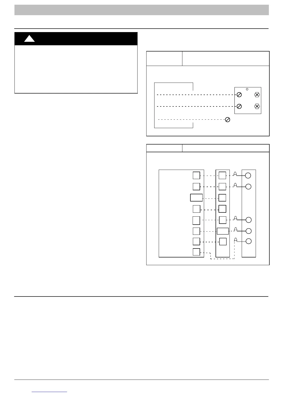
Figure 8
Electrical Supply (Line Voltage)
Connections
DISCONNECT
PER NEC AND/OR
LOCAL CODES
CONTACTOR
GROUND
LUG
FIELD GROUND
WIRING
FIELD POWER
WIRING
11
23 or 13
L1
L2
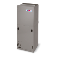
Figure 9 Typical Thermostat Connections
24 VAC HOT
24 VAC COM
R
C
W/W1
R
C
C
THERMOSTAT
HEAT STAGE 1
INDOOR FAN
TWO-STAGE
AIR CONDITIONER
R
Y2
W1
W2
Y1
Y1
W2
Y/Y2
G
G
L
Y
Y2
L
HEAT STAGE 2
LED INDICATOR
LIGHT
COOL STAGE 2
COOL STAGE 1
VARIABLE SPEED
FURNACE /
FAN COIL
AIRFLOW SELECTION
Two-stage compressor operation requires two different
indoor airflow settings for proper operation. This outdoor
unit is designed for use only with an indoor blower that can
be configured for separate low-stage and high-stage
airflow (CFM) levels. Refer to Product Specifications
Sheets for recommended low-stage and high-stage
indoor airflow values. Refer to indoor unit Installation
Instructions to set the indoor blower for the proper
low-stage and high-stage airflow values.
NOTE: Optimal comfort, efficiency, and reliability will only
be achieved when the indoor airflow is properly set for
both low-stage and high-stage operation.