INSTALLATION INSTRUCTIONS R-410A, Two-Stage Split System Air Conditioner
6 421 01 6001 00
!
CAUTION
UNIT OPERATION HAZARD
Failure to follow this caution may result in improp‐
er product operation.
Do not bury more than 36” of line set underground.
Refrigerant may migrate to cooler buried section
during extended periods of unit shut-down, caus‐
ing refrigerant slugging and possible compressor
damage at start-up.
If ANY section of the line set is buried under‐
ground, provide a minimum 6” vertical rise at the
service valve.
D. OUTDOOR UNIT HIGHER THAN INDOOR UNIT
Proper oil return to the compressor should be maintained
with suction gas velocity. If velocities drop below 1500
fpm (feet per minute), oil return will be decreased. To
maintain suction gas velocity, do not upsize vertical
suction risers.
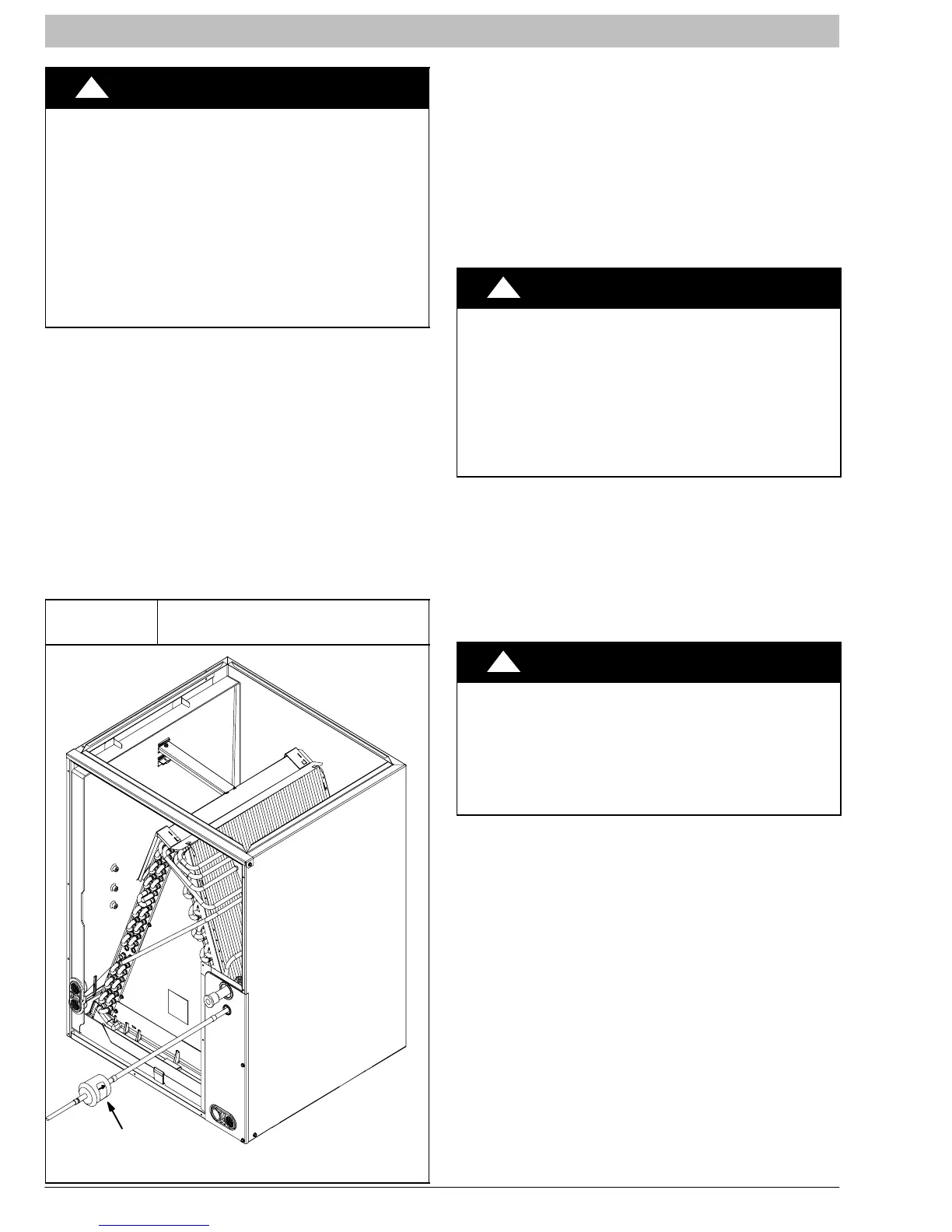
E. LIQUID LINE FILTER-DRIER
Outdoor units are shipped with an appropriate filter-drier
for installation in the liquid line. Leave the plugs in the tube
ends until the filter-drier is installed. The optimal location
for the filter-drier is close to the indoor coil. Install the
filter-drier with the arrow pointing towards the indoor coil.
Refer to Figure 5.
Figure 5
Liquid Line Filter-Drier
Installed at Indoor Coil
38-11-84
Filter-Drier
(arrow points towards indoor coil)
F. SERVICE VALVES
Service valves are closed and tube stubs are plugged
from the factory. Outdoor units are shipped with a
refrigerant charge sealed in the unit. Leave the service
valves closed until all other refrigerant system work is
complete or the charge will be lost. Leave the plugs in
place until line set tubing is ready to be inserted.
Service valve bodies are brass and tube stubs are
copper.
G. BRAZING CONNECTIONS
!
WARNING
FIRE HAZARD
Failure to follow this warning could result in per‐
sonal injury, death, and/or property damage.
Refrigerant and oil mixture could ignite and burn
as it escapes and contacts brazing torch. Make
sure the refrigerant charge is properly removed
from both the high and low sides of the system be‐
fore brazing any component or lines.
Clean line set tube ends with emery cloth or steel brush.
Remove any grit or debris.
Insert line set tube ends into service valve tube stubs.
Apply heat absorbing paste or heat sink product between
service valve and joint. Wrap service valves with a heat
sinking material such as a wet cloth.
Braze joints using a Sil-Fos or Phos-copper alloy.
!
CAUTION
PRODUCT DAMAGE HAZARD
Failure to follow this caution may result in product
damage.
Braze with Sil-Fos or Phos-copper alloy on cop‐
per-to-copper joints and wrap a wet cloth around
rear of fitting to prevent damage to TXV.
H. EVACUATING LINE SET AND INDOOR COIL
The unit is shipped with a factory refrigerant charge. The
liquid line and suction line service valves have been
closed after final testing at the factory. Do not disturb
these valves until the line set and indoor coil have been
evacuated and leak checked, or the charge in the unit
may be lost.
NOTE: Do not use any portion of the factory charge for
purging or leak testing. The factory charge is for filling the
system only after a complete evacuation and leak check
has been performed.