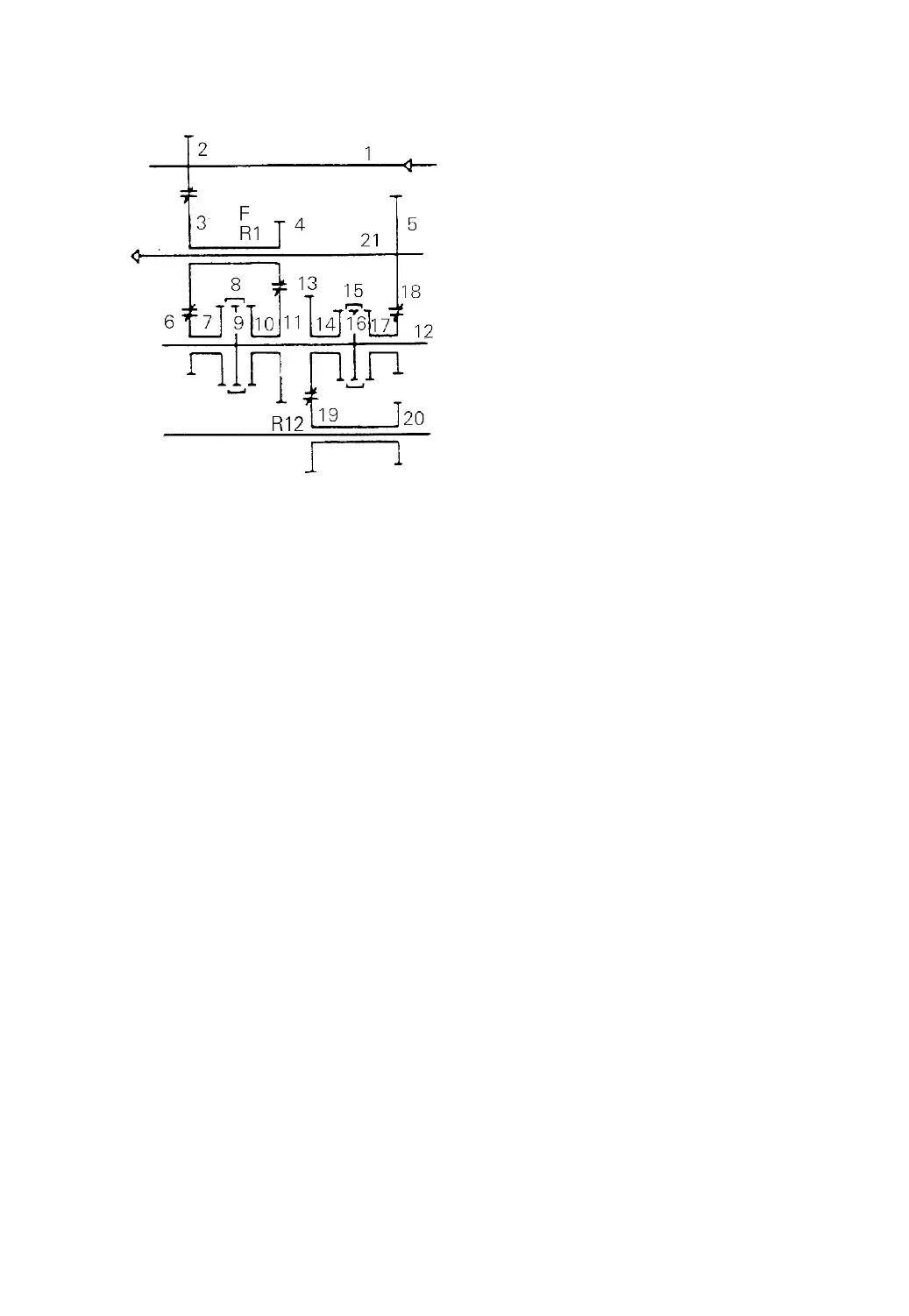
Fig. 3-11
In neutral position —
The power from the driving shaft (1) is transmitted through the input gear, the
cluster gear (3) & (4) to the high speed gear (6) or low speed gear (11). Due to the
mesh sleeve is in the neutral position, the main shaft, output gear and output shaft are
not rotated so the power is not transmitted to the high speed or low speed gear,
Gear shifting —
When the shifting lever is operated, the shift fork moves the mesh sleeve to
allow relative gears to mesh through the synchromesh mechanism. Power is
transmitted in the following order:
Driving shaft-Input gear-Cluster gear-High (or low) speed gear-Synchromesh
mechanism-Main shaft-Synchromesh mechanism-Reverse (or forward) gear-Output
gear- Output shaft.
Power flow in forward 1st speed gear position:
1-2-3-4-11-10-8-9-12-16-15-17-18-5-21
Power flow in forward 2nd speed gear position:
1-2-3-6-7-8-9-12-16-15-17-18-5-21
Power flow in reverse 1st speed gear position:
Power flow
Driving shaft
Output shaft
(1) Driving shaft
(2) Input gear
(3) Cluster gear
(4) Cluster gear
(5) Output gear
(6) High speed gear
(7) Synchronizing cone
(8) Mesh sleeve
(9) Clutch hub
(10) Synchronizing cone
(11) Low speed gear
(12) Main shaft
(13) Reverse gear
(14) Synchronizing cone
(15) Mesh sleeve
(16) Clutch hub
(17) Synchronizing cone
(18) Forward gear
(19) Idler shaft
(20) Idler gear
(21) Output shaft
-24-
 Loading...