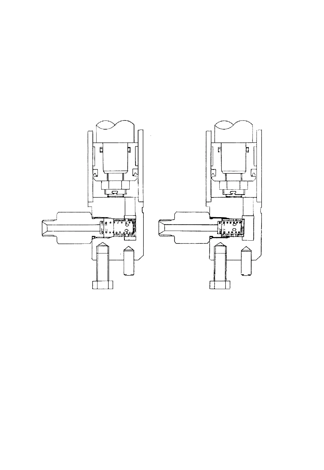
the spring force so that the cut-off valve spool won’t move. If the high-pressure hose
bursts, the pressure difference will be big enough to overcome the spring force,
causing the spool to move until the holes on the circumference on thee spool are
blocked up and allowing only a small amount of oil to flow through the holes at the
spool end to let the forks descend at low speed.
Normal state Working state
Fig.9-9
9.6 Flow Regulator Valve
The flow regulator valve, located in the lift cylinder circuit to limit the
descending speed of loaded forks, has the construction as shown in Fig.9-10. When
the lift spool is placed in the “lift” position, the oil from the control valve flows
through the oil chambers A and B, oil holes C, D, E and F, and the chamber G to the
lift cylinder without any regulation. When the lift spool is placed in the “down”
position, the oil flows in the reverse direction. When the oil passes the orifice plate(5)
and a pressure difference generates between the chambers A and B, the purssure
-79-
 Loading...