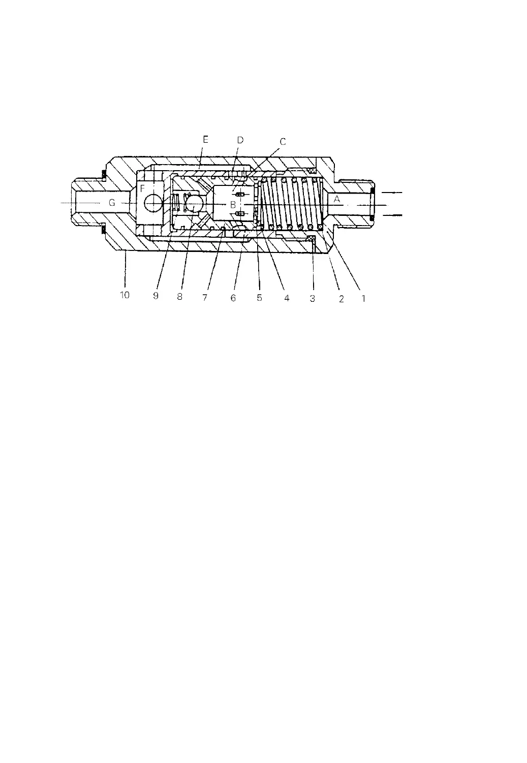
difference overcomes the force of the spring(2) and moves the valve core(7) right,
thus the oil flow being decreased by narrowing of the hole D and C, and reduces the
oil flow passing through the orifice plate(5).
Fig.9-10 Flow regulator valve
(1) Nipple (2) Spring (3) O-ring (4) Snap ring (5) Orifice plate
(6) Sleeve (7) Valve core (8) Ball (9) Spring (10) Valve body
9.7 Tilt Cylinder (See Fig.9-11)
The tilt cylinder is of double-acting type. Each truck has two tilt cylinders which
are installed on two side of the mast assembly with pin while their piston rod ends are
connected with the outer mast channels.
The tilt cylinder assembly consists primarily of piston, piston rod, cylinder body,
cylinder base, guide sleeve and seals. The piston, welded to the piston rod, is fitted
with two Yx-rings and one wear ring on its circumference. A bushing press-fitted to
the inner side of the guide sleeve supports the piston rod. The guide sleeve is fitted
with dust seal, snap ring, Yx-ring and O-ring to prevent oil leakage and keep dust off.
Fitted with them, the guide sleeve is screwed into the cylinder body.
When the tilt lever is pushed forward, the high-pressure oil enters into the
cylinder body from the cylinder tail, moving the piston forward and causing the mast
assembly to tilt forward until 6 degrees. When the tilt lever is pulled backward, high-
pressure oil enters into the cylinder body from the guide sleeve and moves the piston
Normal flow direction
Orifice direction
Control valve
Lift cylinder
-80-
 Loading...