spool, the circuit between the lower part of the lift cylinder and the oil tank is
connected and the piston begins to descend due to the weight of the load and all of
lifting parts. In this case, the oil flow returning to the control valve is regulated by the
flow regulator valve and the fork descent speed is controlled. When the tilt lever is
operated, the high pressure oil reaches the front or rear chamber of the cylinder and
pushes the piston forward or backward. The oil pushed out by the piston returns to the
oil tank through the control valve and the mast then tilts forward or backward.
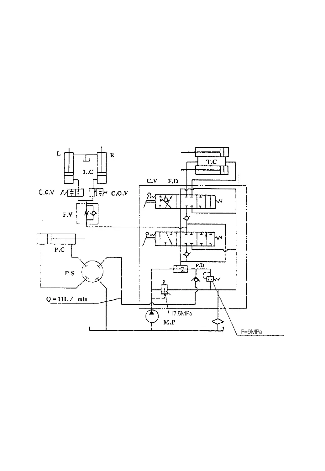
Fig.9-7 Hydraulic oil circuit
T.C.- Tilt cylinder L.C.- Lift cylinder C.V.- Control valve F.D.- Flow
divider
F.V.- Flow regulator valve C.O.V.- Cut-off valve P.C.- Power steering cylinder
P.S.- Power steering unit M.P.- Main pump L.- Left R.- Right
9.5 Lift Cylinder(See Fig.9-8)
The two single-acting type lift cylinders are located behind the outer mast
-76-
(2-3.8t)
(2-3.8t)
 Loading...