13
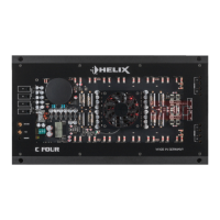
Initial start-up and functions
1
Remote
This input is used to connect an optionally avail-
able remote control. The remote control allows you
to control the volume of the channels C and D in
stereo and bridged mode.
Note: Volume control via remote control is only ac-
tivated in bandpass mode.
2
Mode Input
This switch is used to route the input signals to the
respective amplier channels.
4-channel mode: If the head unit / car radio provides
two stereo outputs (front left / right, rear left / right),
all four signal inputs of the amplier are supplied
with the corresponding output signals of the head
unit / car radio.
2-channel mode: If the head unit / car radio only
provides one stereo output, all amplier channels
are supplied with this signal. This means, that only
the RCA / highlevel inputs of the channels A and B
need to be connected. In this mode the input signal
of channel A is routed to channel C and channel
B is routed to channel D. Please consider that the
fader and balance control of the head unit have the
same effect on channels A and C and respectively
B and D.
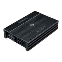
3
Bass Boost
This control is used to increase the bass response
at a center frequency of 45 Hz from 0 to 12 dB.
4
Line Input
4-channel lowlevel line input to connect signal
sourc es such as head units / radios / DSPs.
Important: It is strictly forbidden to use the High-
level Input and lowlevel Line Input at the same time.
This may cause severe damage to the lowlevel line
outputs of your head unit / car radio.
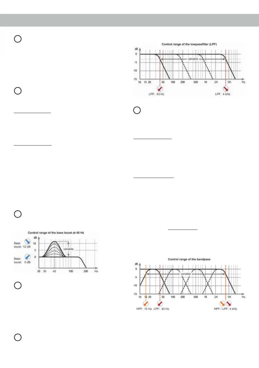
5
LPF
This control is used to adjust the crossover frequen-
cy of the lowpass lter of the channels C and D from
40 Hz to 4,000 Hz.
6
X-Over
This switch allows to set the internal crossover to
highpass, fullrange or lowpass / bandpass mode.
The lter options depend on the channel pair.
Channel pair A/B: Highpass lter or fullrange
If this X-Over switch is set to HPF (highpass lter)
the crossover frequency for the highpass can be ad-
justed with control 7 of the channel pair A/B.
At switch position FULL (fullrange) the crossover is
bypassed.
Channel pair C/D: Lowpass lter / bandpass, full-
range or highpass lter.
If this X-Over switch is set to HPF (highpass lter)
the crossover frequency for the highpass can be
adjusted with control 7 of the channel pair C/D. At
switch position FULL (fullrange) the crossover is
bypassed.
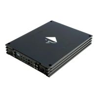
At switch position LPF (lowpass lter / bandpass)
the highpass is always active. That means a band-
pass is created in any case.
By adjusting the highpass (control 7) and lowpass
(control 5) lter any bandpass between 15 Hz and
4,000 Hz can be realized.
Caution: To avoid a loss of gain make sure that
the crossover frequencies of the high- and lowpass
lters do have an interval of at least two octaves
when generating a bandpass.
That means if the lowpass signal is adjusted to
320 Hz the highpass should be adjusted to 80 Hz