H220 Integrator Guide Chapter 2
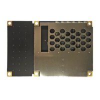
Board Overview
Page 11 of 28
Connectors
Table 2-1 describes the H220’s connectors and the mating connectors. You can use different
compatible connectors; however, the requirements may be different. The antenna input
impedance is 50 Ω.
Table 2-1: H220 Connectors
Connector H220 SMT Connector Mating Connector
RF MCX, straight jack (female)
(Molex 73415-1692)
MCX, straight plug (male)
(AMP: 1061015-1)
Interface 17x2 pin header plug (male)
0.05 in (1.27 mm) pitch
(Samtec: FTSH-117-04-G-DV-P-TR)
17x2, SMT header socket (female)
0.05 in (1.27 mm) pitch
(Samtec: FLE-117-01-G-DV)
Mounting Options
There are two options for mounting the H220:
Direct Electrical Connection method
Indirect Electrical Connection (Cable) method
Direct Electrical Connection Method
Place an RF connector, heading connector, and mounting holes on the carrier board and then
mount the H220 on the standoffs and RF header connectors. This method is very cost effective
as it does not use cable assemblies to interface the OEM board.
The H220 uses a standoff height of 0.79 cm (0.3125 in). With this height, there should be no
washers between either the standoff and the H220 or the standoff and the carrier board;
otherwise, you must make accommodations. You may need to change the standoff height if you
select a different header connector.
If you want to use a right angle MCX connector, use a taller header than the Samtec part number
that Hemisphere suggests. This will provide clearance to have a right-angle cable-mount
connector and reduce the complexity by not having the carrier board handle the RF signals. See
Table 2-1 on for H220 connector information.
The mounting holes of the H220 have a standard inner diameter of 0.32 cm (0.125 in).
Indirect Electrical Connection (Cable) Method
The second method is to mount the H220 mechanically, so you can connect a ribbon power/data
cable to the H220. This requires cable assemblies and there is a reliability factor present with
cable assemblies in addition to increased expense.
Note: Be aware of the GPS RF signals present on the carrier board and ensure the correct
standoff height to avoid any flexual stresses on the board when fastening.