Seite1/7 Sach-Nr. 2 727 022 Version 1250899MW
operating instructions
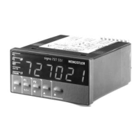
signo 727 SSI
Position-Indicator with/without limit
values and SSI input from absolute
encoder
1. Safety instructions
This instrument has been built and tested in
accordance with EN 61010, part1 - Protection
Measures for Electronic Measuring Instruments -
and have left our works in safe and proper condition.
In order to maintain these conditions and to ensure
safe operation, the user must observe the
instructions and warnings provided in these
operating instructions.
• This units must only be operated if correctly
installed!
• The supply voltage must be derived from a SELF
SOURCE (12-24VDC versions) according to EN 60
950, since no galvanic separation is provided
between power-supply and electronic in-/outputs!
• When mounting and installing the units, the
instructions of the local suppliers of energy are to
be considered.
• The unit must only be opened for setting by trained
personnel.
• The plug-in terminals, at rear of the unit, must not
be accessed before first isolating the supply.
• The identification numbers of the plug-in terminals
and of the corresponding socket strip must be
observed.
• Unassigned terminals (NC) may not be connected!
• Connection terminals are to be protected by
installation!
Contents
1. Safety instructions 1
2. Mounting of the position indicator 2
2.1 Mounting and dimensional drawing 2
2.2.1 Connections 2
2.2 Terminal connections 2
2.2.2 Description of inputs and outputs 3
2.3 Description of function of position
indicator 3
3. Operation of the position indicator 3
3.1 Display and keyboard 3
3.2 Setting the reference value and resset
of the chain value 3
3.3 Changing limit value 1and 2 and set
value 4
4. Programming 4
4.1 Survey 4
4.2 Display of the absolute data of the
absolute shaft encoders 5
4.3 Changing system parameters 5
4.4 Survey on the system parameters
and alternatives 5
5. Locking of keyboard functions 6
6. Failures and error messages 6
7. Technical data 6
7.1 Ordering information 7
7.2 Accessories 7
7.3 Explanation of technical terms 7
• In order to ensure hand contact safety at the
connection terminals, live wires must be con-
nected properly to the connection terminals.
• If safe operation can no longer be ensured, the
position indicator must be disabled and secured
against accidential operation.
• Installation of electrical devices should only be
carried out by a qualified electrican.
• Panel mounting devices should only be operated
when proberly mounted in the panel
• Before switching on, make sure that the power and
control voltages do not exceed the values specified
in the technical data.
• In a situation where failure of the device could
cause harm to people, animals or property,
additional safety measures must be employed,
e.g. stop switches, protection devices etc.
• Hengstler counters are intended for industrial
applications.
• The mounting and environment and nearby cabling
have an important influence on the EMC (noise
radiation and noise immunity) of the counter.
When putting into operation, the EMC of the whole
installation (unit) has to been secured. In
particular, the relay outputs are to be protected
from high noise radiation by suitable wiring.