Do you have a question about the Henry Radio 2K-Classic and is the answer not in the manual?
Describes the type and function of the linear RF amplifiers.
Specifies the types of radio emission supported by the amplifiers.
Details the nominal and peak output power ratings for the amplifiers.
Specifies the required input drive power for the amplifiers.
Provides the physical dimensions for each amplifier model.
Lists the shipping weight for each amplifier model.
Outlines the duty cycle specifications for continuous or intermittent service.
Details the AC voltage and current requirements for operation.
Explains the function of the Automatic Level Control circuit.
Describes the cooling method used in the amplifiers.
Indicates the nominal average plate power input.
Specifies the operating frequency bands for the amplifiers.
States the nominal input impedance of the amplifiers.
States the nominal unbalanced output impedance.
Identifies the type and number of tubes used in the amplifiers.
Details the specifications for harmonic and spurious radiation.
Specifies the noise level of the amplifier.
Lists the plate voltage ranges for different modes and models.
Describes the construction of the amplifier cabinets.
Explains the built-in antenna relay system.
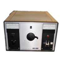
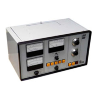
Lists the parameters that are metered.
Describes the protection mechanisms used in the amplifier.
Lists the accessories included with the amplifier.
Instructions for unpacking the amplifier and checking for damage.
Guidance on selecting a suitable location for the amplifier.
Step-by-step procedure for installing the vacuum tubes.
Details on connecting the power, antenna, and control cables.
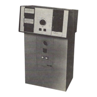
Describes the controls located on the front panel of the amplifier.
Describes the connectors and controls on the rear panel.
Initial setup and settings before operating the amplifier.
Procedure for operating the amplifier in Single Sideband mode.
Procedure for operating the amplifier in Continuous Wave mode.
Instructions for adjusting the Automatic Level Control.
An alternative method for tuning the amplifier for maximum output.
Important safety and operational precautions to follow.
Troubleshooting steps for input mismatch issues.
Common problems related to vacuum tubes and their solutions.
Troubleshooting steps for issues with the relay circuit.
Troubleshooting steps for high voltage circuit issues.
Troubleshooting steps for problems with the cooling blower.
Troubleshooting steps for low output power issues.
Information on AC line voltage compensation and its effects.
Addresses other miscellaneous problems and their solutions.
Guidance on how to contact the factory for service.
Procedures for disassembling the desk model amplifier.
Procedures for disassembling the floor console amplifier.
List of part numbers for blower components.
List of part numbers for capacitor components.
List of part numbers for diode components.
List of part numbers for fuse components.
List of part numbers for connector components.
List of part numbers for knobs.
List of part numbers for inductor components.
List of part numbers for resistor components.
List of part numbers for relay components.
List of part numbers for switch components.
List of part numbers for potentiometer components.
List of part numbers for tube components.
List of parts related to the power supply section.
Details the terms and conditions of the limited warranty.
| Input Impedance | 50 ohms |
|---|---|
| Power Output | 2000 W PEP |
| Cooling | Forced air |
| Plate Voltage | 3000 V |
| Drive Power | 100 W |
| Input Power | 100 watts |