EasyManua.ls Logo

Henry Radio 8K Ultra User Manual

Default Icon
46 pages
To Next Page IconTo Next Page
Page #1 background imageLoading...
Page #1 background image
Question and Answer IconNeed help?

Do you have a question about the Henry Radio 8K Ultra and is the answer not in the manual?

Henry Radio 8K Ultra Specifications

General IconGeneral
CoolingForced air
ModeSSB, CW, AM
RF Output Power8000 W PEP
Input Impedance50 ohms
Output Impedance50 ohms
Power Requirements240 VAC
Voltage240 VAC

Summary

The Importance of Amplifier Tuning

Warranty and Safety Information

Manufacturer's Instructions

Operator precautions for installing and operating the unit safely.

User's Responsibility

Outlines the user's role in correcting RFI and potential troubleshooting steps.

Section 1: Henry 3K Ultra and 8K Ultra Specifications

Key Equipment Specifications

Covers type, output power, frequency range, tube complement, dimensions, and AC mains.

Section 2: 3K/8K Ultra Features

Remote Operation and Control Features

Details remote operation, metering, and control functions.

Connectivity, Protection, and Power Systems

Explains connections, safety features, and power supply characteristics.

Section 3: Introduction

Amplifier Design and Operation Overview

Discusses the grounded grid design, components, and basic setup needs.

Model Specifics and Safety Cautions

Details model differences and critical safety warnings.

Section 4: Installation

Unpacking, Accessories, and Location

Instructions for unpacking, checking accessories, and selecting an operating environment.

Cabling and Power Connection Procedures

Details on connecting power cables and ensuring proper grounding.

Connector Installation and Operating Precautions

RF Output Connector Preparation

Detailed procedure for preparing and attaching an N-type connector.

SWR and Load Operating Warnings

Critical warnings about operating into improper loads and SWR limits.

Interconnection and Transformer Tap Settings

Transceiver Interfacing and Relay Keying

Explains how to connect the amplifier to a transceiver for keying and ALC.

Transformer Tap Configuration Guide

Instructions for setting primary voltage taps on high voltage and filament transformers.

Figure 4.2: Transformer Tap Diagram

Section 5: Operating Controls

Controller Front Panel Controls

Describes Power, Multimeter, Tune, Load, and Band switches.

Band Switch and CW/SSB Settings

Provides frequency ranges and explains CW/SSB switch functions.

Section 5.2: Rear Panel Controls and Connections

ALC, Relay, RF, and Ground Connections

Explains ALC feedback, relay control, RF jacks, and grounding.

Henry 3K Ultra and 8K Ultra Interconnect Diagram

Operating Controls: Controller Layouts

Controller Front Panel Diagrams

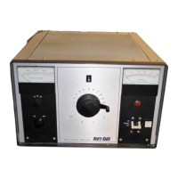
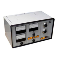
Shows variations of controller front panels with labeled controls.

Standard Controller Rear Panel View

Depicts the rear panel of the standard controller with connection ports.

Operating Controls: Controller Top Views

Controller Top Views (Door Open/Closed)

Diagrams showing the top of the controller with and without the access door open.

Console Operating Controls

Console Front Panel Layout

Shows the front panel of the console with controls and indicators.

Console Back Panel Connections

Details the rear panel connections for the console unit.

Section 6: Operation

Preliminary Settings and CW Operation

Steps for initial setup and performing CW tuning.

CW Tuning Procedure Details

Detailed steps for tuning the amplifier for CW output.

Operation Precautions and SSB Tuning

SSB Operation and ALC Setup

Procedures for tuning in SSB mode and adjusting the ALC circuit.

General Operating Precautions

Essential safety advice for amplifier operation and maintenance.

Preset Option Usage and Setup

How to use and set up the optional preset tuning channels.

Section 7: Maintenance/Troubleshooting

General Maintenance and Input Mismatch

Basic maintenance checks and troubleshooting input mismatch problems.

Relay Problems Troubleshooting Guide

Identifies symptoms and probable causes for relay-related issues.

Troubleshooting: Tube, HV, and Blower Issues

Tube and High Voltage Problem Diagnosis

Diagnosing issues with tubes, high voltage circuits, and circuit breakers.

Blower Operation and Noise Troubleshooting

Troubleshooting steps for blower operation and noise issues.

Troubleshooting: Output, AC Line, and Other Issues

Output and AC Line Voltage Problems

Solutions for low output, AC power issues, and amplifier not turning on.

Factory Support and Contact Information

Information on how to obtain assistance from Henry Radio for servicing.

Henry 3K/8K Ultra Interconnect Schematic

Controller and Amplifier Wiring Diagram

Shows the pin assignments and connections between major units.

Henry 3K Ultra and 8K Ultra Control Cable Pin Wiring

Desk Top Controller Schematic (Standard Configuration)

Desk Top Controller Schematic (5 Channel Preset Configuration)

Parts List for 3K Ultra Desk Top Controller

Parts List for 8K Ultra Desk Top Controller

Henry 3K Ultra RF Deck Schematics and Parts List

3K Ultra RF Chassis Layout Diagram

Diagram showing the physical layout of components on the 3K Ultra RF chassis.

3K Ultra RF Deck Schematic

Parts List for 3K Ultra RF Chassis

8K Ultra RF Deck Schematic

Parts List for 8K Ultra RF Chassis

Parts List for 3K Ultra Power Supply

Henry 3K Ultra Power Supply Layout

Henry 8K Ultra Power Supply Layout

3K Ultra Power Supply Schematic (1 Phase)

8K Ultra Power Supply Schematic (1 Phase)

Parts List for 8K Ultra Power Supply (1 Ph)

Parts List for 8K Ultra Power Supply (3 Ph)

8K Ultra Power Supply Schematic (3 Phase 220 VAC)

Henry PCB Power Supply Schematics

PCB1104 Wheatstone Bridge Controller Supply

Schematic for the power supply of the Wheatstone bridge servo motor controller.

PCB1105 26v Relay Supply

Schematic for the 26VDC relay supply module.

Henry PCB1104 Wheatstone Bridge Servo Motor Controller

Henry PCB1102 13.8 VDC Power Supply

Henry 3K Ultra and 8K Ultra Tube Specifications

3K Ultra 3CX1200D7 Tube Details

Specifications for the 3CX1200D7 ceramic triode power tube.

8K Ultra 3CX3000A7 Tube Details

Specifications for the 3CX3000A7 ceramic triode power tube.

Related product manuals