Do you have a question about the Henry Radio 2KD-Classic and is the answer not in the manual?
Describes the models (2K-Classic, 2KD-Classic, 2K-Classic X) and their intended use.
Details the power output capabilities and necessary input drive power for the amplifiers.
Covers dimensions, shipping weight, duty cycle, power requirements, and cooling.
Specifies the operating frequency bands and allowed types of emission (SSB, AM, CW, RTTY).
Lists the vacuum tubes used and limits for harmonic and spurious radiation.
Information on plate voltage ranges and the construction of amplifier cabinets.
Describes the metering systems, protection devices, and included accessories.
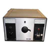
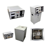
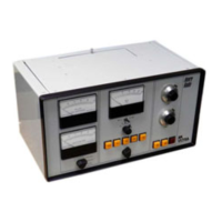
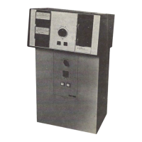
Introduces the 2K-Classic family, their common design, and differences between models.
Critical caution regarding high voltages and lethal shock hazards present in the amplifier.
Procedures for removing the amplifier from its packaging and checking for shipping damage.
Guidelines for choosing a suitable location with adequate airflow and power supply.
Step-by-step instructions for safely inserting the 3-500Z tubes into their sockets.
Instructions for connecting the power cable and signal cables (RF, ALC, Relay) to the amplifier.
Detailed explanation of the function, multimeter, meters, and switches on the front panel.
How to use the Tune, Load, and Band controls for adjusting amplifier operation.
Identifies rear panel connectors for RF, ALC, and relay, along with fuse locations.
Details on connecting the power cord and adjusting voltage via terminal boards.
Steps for initial setup, verifying blower, checking high voltage, and assessing tube condition.
Step-by-step guide for tuning the amplifier for optimal output in SSB and CW modes.
Instructions for setting ALC and an alternate method for tuning for maximum output.
Essential safety warnings and precautions to ensure safe and reliable operation.
Troubleshooting steps for input mismatch issues.
Diagnosing and resolving common tube-related problems like excessive plate current or shorts.
Troubleshooting steps for issues with the amplifier's relay circuit.
Diagnosing and resolving common high voltage issues like shorts, low, or excessive voltage.
Troubleshooting steps for blower failures or damage.
Steps to diagnose and fix low output issues, including drive and cabling.
Information on compensating for variations in AC line voltage.
Addresses miscellaneous issues like ALC circuits, filament failure, and amplifier not turning on.
Instructions on how to contact the factory for servicing or returning the unit.
Detailed instructions for disassembling the desk model amplifier.
Detailed instructions for disassembling the floor console model amplifier.
Lists components for RF sections: blowers, capacitors, diodes, fuses, connectors, knobs, inductors.
Lists components for power supply sections: capacitors, breakers, diodes, fuses, connectors, inductors, meters, lamps, resistors, switches, transformers.
Provides approximate factory settings for tune and load dials for a 52 ohm load across bands.
A section for users to record their own tune and load settings and observed output.
Outlines the limited warranty provided by Henry Radio, including coverage and duration.
Details specific exclusions, such as misuse, unauthorized repairs, and limitations on damages.
| Brand | Henry Radio |
|---|---|
| Model | 2KD-Classic |
| Category | Amplifier |
| Language | English |