User manual // Integra Plus // Compact flash unit
36 HENSEL-VISIT GmbH & Co. KG
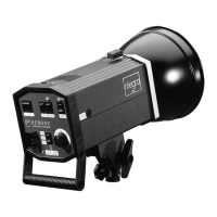
6 Overview of controls
Compact flash unit – controls front panel
1 ON: main switch ON / OFF
2 RC*: remote control switch and ON indicator
3 AUDIO: acoustical ready signal and ON indicator
4 FC: flash check switch and ON indicator
5 SLAVE: slave switch and ON indicator
6 TEST: Manual flash release with ready indicator
7 Sync socket
8 Slave
9 Fuse 4 A
10 Mains connector (Bi-voltage 110 V and 230 V)
11 FULL: modeling lamp operation mode and ON indicator
12 PROP: modeling lamp operation mode and ON indicator
13 Flash power control switch
14 LED display
Tilting head – components
15 Cable fixation
16 Hole of the umbrella holder
17 Shifting of the tilting head to balance heavy loads
18 Clamping screw to hold umbrellas
19 Star screw for attaching unit to a stand
20 Fixing bracket
Radio transmitter – controls*
21a Flash power down and modeling light options
21b Flash power up button
22 Channel selector for 3 channels / ‘All’ option (sliding switch)
23 Test button for flash triggering
24 Socket for sync cable, Ø 2.5 mm
25 Locking screw for mounting to the hot shoe of the camera
26 Screw for opening the battery compartment
*: The radio transmitter is not included in the standard delivery and has to
be ordered separately. (Code no. 3950 or 3955)