Page 8 For technical questions, please call 1-888-866-5797. Item 56435
Specifications
Electrical Rating 120 VAC / 60 Hz / 7 A
No Load Speed 11,000 RPM
Spindle Thread
5/8"- 11 TPI with
7/8" Adaptor
Max. Accessory Diameter 4-1/2" (115 mm)
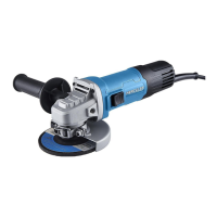
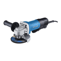
Functional Description
1
2
3
4
5
6
1. Side Handle
2. Spindle Lock
3. Slide Switch
4. Wheel Guard
5. Wheel Guard Bolt
6. Wheel Guard Lock Lever
OPERATION
Read the ENTIRE IMPORTANT
SAFETY INFORMATION section at the
beginning of this manual including
all text under subheadings therein
before set up or use of this product.
Tool Set Up
TO PREVENT SERIOUS INJURY FROM
ACCIDENTAL OPERATION:
Make sure that the Switch is in the OFF position and
unplug the tool from its electrical outlet before
performing any procedure in this section.
Adjusting the Wheel Guard
TO PREVENT SERIOUS INJURY:
Do not operate this tool without the
Wheel Guard properly installed.
1. Pull out the Wheel Guard Lock Lever.
2. Rotate the Wheel Guard as needed to
shield you during the planned work.
3. Push the Wheel Guard Lock Lever back
into place to secure the Wheel Guard.
4. Check the Wheel Guard to ensure it is firmly in place.
Adjust if necessary before proceeding.
Installing Auxiliary Side Handle
TO PREVENT SERIOUS INJURY:
Do not operate this tool with one hand only or
without the Side Handle properly installed.
1. The Side Handle may be installed in one of two
positions, on either side of the Gear Housing.
2. Screw the threaded end of the Side Handle
clockwise into the selected position.
Tighten securely before beginning work.
Side
Handle
Side Handle Socket