14
for the technician
Installation instructions
A qualified technician must check that the electrical system is in line with the maximum power
allowed by the boiler, indicated on the data plate, with particular attention to the cables section.
Remark: HERMANN Ltd. declines any responsibility for damages to persons, animals or
things caused by the non-connection of the boiler earthing and by failure to comply with
the rules.
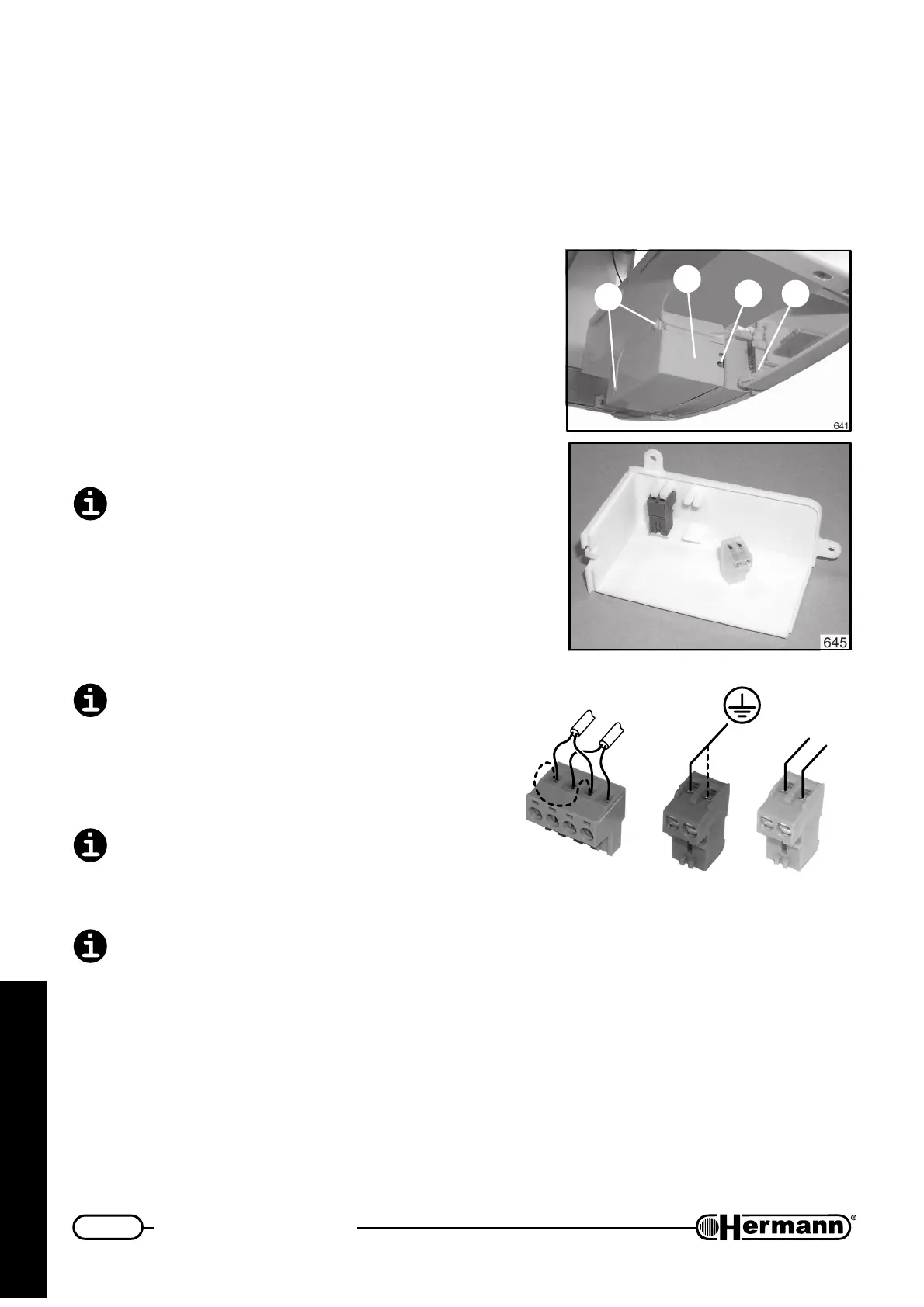
ELECTRICAL CONNECTIONS TO THE BOILER
— Unscrew the two screws [1] and remove cover [2];
— extract yellow and white connectors;
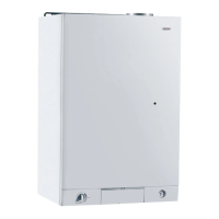
— make electric connections as shown in the picture
situated on the other side of the cover:
• connect earth wire to yellow connector;
• connect NEUTRAL cable (N) and PHASE (L)
to WHITE connector, precisely as shown in
the picture;
If PHASE and NEUTRAL wires are reversed,
the boiler will not work.
• when a Room Thermostat or Chrono
Thermostat (TA) and/or Outdoor Temperatu-
re Probe (SE) are foreseen, unplug GREEN
connector from PCB and make connections
as shown in the picture. If TA is installed,
disconnect jumper [X].
TA and SE terminals on green connector work
at low voltage: only connect NON POWERED
wires coming from simple contact of Room
Thermostat / Chrono Thermostat, and/or
Outdoor Temperature Probe. DO NOT connect
live wires, for any reason.
Original Hermann remote control (optional kit)
must NOT be connected to green connector.
Special interface card, supplied in the remote
control kit, must be used.
All low-voltage wirings (e.g. TA, SE and original Hermann remote control) must be kept sepa-
rate from power supply cables, as to avoid boiler malfunctionings due to electrical noise. It is
advisable to use separate tubes for them.
— all the relevant connections must be inserted in modulation PCB, FOLLOWING THE CORRECT
COLOURS. They have been provided with special plugs for correctly connect them.
— close cover inserting cables in the provided holes [3] and screw the screws [1];
— block cables with the special device [4].
1
2
3
4
TA
X
SE
642_R01
L
N