The HLK-LD012-5G is an ultra-low power 5.8G radar sensor module developed by Hilink Electronics, designed for various sensing applications, particularly in smart home, Internet of Things (IoT), and smart lighting contexts. Its compact size and low power consumption make it especially suitable for battery-powered devices like night lights, solar street lights, and wireless cameras.
Function Description:
The HLK-LD012-5G module integrates a 5.8GHz microwave circuit, an intermediate frequency amplifier circuit, and a signal processor. This comprehensive integration ensures high performance and consistency in production. The primary function of the module is to detect the presence of human bodies or other moving targets. It achieves this by emitting microwave signals and analyzing the reflected signals to identify motion within its detection range. The module features a planar antenna, which contributes to its compact form factor and helps maintain sensor performance while minimizing overall size.
The module incorporates a power-on self-check function. Upon power-up, the OUT pin initially outputs a high level, then transitions to a low level after a 2-second delay, and subsequently enters the normal induction mode after an additional 0.5-second delay. This sequence ensures proper initialization before active sensing begins.
Important Technical Specifications:
- Power Consumption: Approximately 68uA (ultra-low power).
- Module Size: 20mm x 20mm.
- Thickness: 2.5mm (without pins). If pins are added, the default pin height is 12mm.
- Pin Distance: 2.54mm.
- Transmit Frequency: 5725 MHz (minimum) to 5875 MHz (maximum).
- Transmit Power: 0.2 mW (typical) to 0.5 mW (maximum).
- Input Voltage (VIN): 2.7V (minimum) to 4.8V (maximum) for direct power supply (e.g., lithium or dry battery) when LDO is not attached. If an LDO is added (for power supply voltage exceeding 5V), the VCC can be 5V to 12V.
- Output High Level: 2.2V.
- Output Low Level: 0V.
- Working Current: 68 uA (typical) to 75 uA (maximum) (average working current).
- Hanging Height: 8M (typical) to 10M (maximum) (forward sensing distance).
- Sensing Radius: 15S (adjustable according to specific needs).
- Delay Time: 10 Lux (adjustable according to specific needs).
- Photosensitive Threshold: -30 °C (minimum) to 85 °C (maximum).
- Output Signal: High and low level (0V/2.2V).
Usage Features:
The HLK-LD012-5G module offers several features for customization and flexible deployment:
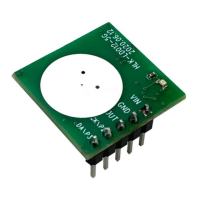
- Pin Configuration: The module has five pin holes: VIN, GND, OUT, P2, and P3.
- VIN: Module power supply. By default, an LDO is not attached, allowing direct power supply from 2.7V to 4.8V. For voltages exceeding 5V, an external LDO is required, and the VCC supply can be 5V to 12V.
- GND: Grounded pin.
- OUT: Output signal, providing high and low levels (0V/2.2V) to indicate detection.
- P2 (GPIO2): Used for receiving gain gear selection, which directly impacts the sensing distance.
- P3 (GPIO3): Used for delay time gear selection, controlling the duration of the OUT signal's pull-up after detection.
- Sensing Distance Adjustment: The P2 pin allows for adjusting the sensing distance. The module provides 16 different sensing distance options, configurable via three reserved resistors (th0, th1, th2).
- When P2 is suspended or pulled up, the sensing distance is maximized.
- When P2 is pulled down, the receiving gain is reduced by 18dB, resulting in a shorter sensing distance.
- The three distance adjustment resistors on the module modify the inductive judgment threshold. A smaller threshold corresponds to a farther sensing distance. The resistance bits are interpreted as NC (Not Connected) for '1' and 0 ohm for '0'.
- Delay Time Adjustment: The P3 pin controls the pull-up time of the OUT signal after sensing.
- If P3 is floating or pulled high, the sensing pull-up time is 2 seconds.
- If P3 is pulled low, the sensing pull-up time is 15 seconds.
- A new trigger during the inductive output pull-up period will extend the inductive time.
- Photosensitive Detection (Optional): The module supports photosensitive detection, though it is not enabled by default in sample modules. When enabled, the radar sensor will only activate if the ambient light level is below a set illuminance threshold. This feature is useful for applications where sensing is only required in low-light conditions. The photosensitive threshold can be adjusted by changing the judgment threshold or tuning the photosensitive resistance. If the light is too bright, the sensor function will not activate.
- Detection Range: The sensing sensitivity can be configured by adjusting resistance. The positive limit sensing distance is 10 meters, but the actual sensing distance can be adjusted as needed. The detection range typically shows a high sensitivity area (dark area in diagrams) where objects are fully detected, and a low sensitivity area (light color area) where objects are generally detected. Setting higher sensitivity increases the detection range.
Maintenance Features:
The manual outlines several precautions for proper installation and operation, which can be considered maintenance-related to ensure optimal performance and longevity:
- Antenna Placement: Avoid placing metal shells or components directly in front of the antenna to prevent signal shielding. Plastic or glass obstructions are permissible but should not be too close to the antenna.
- Interference Avoidance:
- Try to avoid directing the radar antenna towards large metal equipment or pipelines, as these can interfere with radar signals.
- The radar sensor should be kept away from AC drive power supplies and rectifier bridges of drive power supplies to prevent power frequency interference with radar signals.
- Multi-Module Installation: When installing multiple radar modules, ensure their antennas are parallel to each other. Avoid direct illumination between antennas and maintain a distance of more than 1 meter between modules to prevent mutual interference.
These guidelines help in maintaining the module's performance and preventing common issues related to installation and environmental factors.