Shenzhen Hi-Link ELectronics Co.,Ltd
User Manual
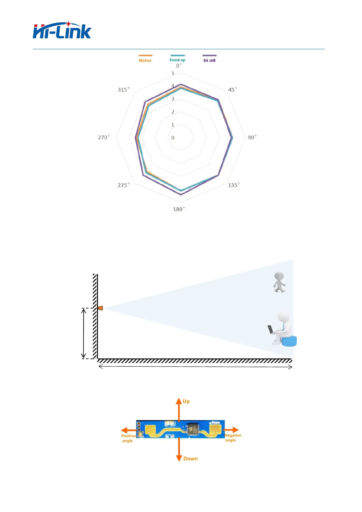
(Distance unit: meters, Angle unit: degrees)
Figure 8 Schematic Diagram of the Detection Range (the ceiling height is 3 meters)
(Distance unit: meters, Angle unit: degrees)
Figure 9 Schematic Diagram of Wall-mounted Installation
 Loading...