Shenzhen Hi-Link ELectronics Co.,Ltd
User Manual
Content
1 Product Introduction ..........................................................................................................1
2 Product Features and Advantages .................................................................................... 2
2.1 Features ................................................................................................................................ 2
2.2 Solution Advantages .............................................................................................................2
3 Application Scenarios .........................................................................................................3
4 Hardware Description ........................................................................................................ 4
4.1 Dimensions ........................................................................................................................... 4
4.2
P
in Definition ....................................................................................................................... 4
5
U
sage and Configuration ................................................................................................... 5
5.1 Typical Application Circuit .................................................................................................. 5
5.2 The Role of Configuration Parameters ................................................................................. 5
5.3 Visual Configuration Tool Description ................................................................................ 6
5.4 Mounting Method and Sensing Range ..................................................................................7
5.5 Installation Conditions ..........................................................................................................9
6 Performance and Electrical Parameters .........................................................................10
7 Radome Design Guidelines .............................................................................................. 11
7.1 Effects of Radomes on mmWave Sensor Performance ...................................................... 11
7.2 Radome Design Principles ..................................................................................................11
7.3 Common materials ..............................................................................................................12
8
R
evision History ................................................................................................................12
9 Technical Support and Contact .......................................................................................13
Chart Index
Table 1 Pin Definition Table .......................................................................................................... 5
Table 2 Performance and Electrical Parameters Table .................................................................10
Table 3 Common Material Properties of Radomes ...................................................................... 12
Figure 1 Diagram of Usage ............................................................................................................ 1
Figure 2 Comparison of mmWave Radar Scheme and Other Schemes .........................................3
Figure 3 Application Scenario ........................................................................................................4
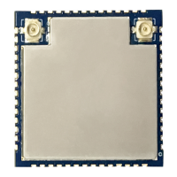
Figure 4 Physical Map of the Module ............................................................................................ 4
Figure 5 Module Dimensions ......................................................................................................... 4
Figure 6 Module Pin Definition Diagram ...................................................................................... 4
Figure 7 Schematic Diagram of Ceiling-mounted Installation ...................................................... 7
Figure 8 Schematic Diagram of the Detection Range (the ceiling height is 3 meters) .................. 8
Figure 9 Schematic Diagram of Wall-mounted Installation .......................................................... 8
Figure 10 Schematic Diagram of Detection Range (wall-mounted height is 1.5 meters) ..............9
Figure 11 Measured Data of Module Working Current ............................................................... 10
 Loading...