HID Aero™ X100 Installation Guide
PLT-04234, Rev. A.32
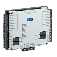
Powering
Trusted Identities
RS-485
termination jumper
ATTENTION
Observe precautions for handling
ELECTROSTATIC SENSITIVE DEVICES
Always mount the controllers and interface panels in
a secure area.
Mount using the supplied screws 0.138" × 1"
(3.5 mm × 25 mm).
Alternatively mount on a DIN rail using compatible
DIN rail mounting brackets and screws.
See Recommended parts.
Note: The side terminal connectors must be
removed to fit the mounting brackets.
Port 1 to serial IO devices Port 2 to serial IO devices
To other
devices
on the bus
To other
devices
on the bus
1. Mounting the X100
2. Communication wiring
Connect the X100 to the Aero X1100 intelligent
controller using IO Module ports (2-wire RS-485).
Use 1-twisted pair, shielded cable, 120Ω impedance,
24 AWG, 4,000 ft. (1,219 m) maximum.
Note: Both IN and OUT terminals on the IO MODULE
are the same port and are internally connected.
Setting the termination jumpers
Install RS-485 termination jumpers on the interface
boards at each end of the communication bus only.
Failure to do so will compromise the proper operation
of the communication channel.
JUMPER DESCRIPTION
IN
Install only on the first and last unit on the
communication bus.
OUT
Install only if not the first or last unit on the
communication bus.
IO MODULE IN or IO MODULE OUT
 Loading...