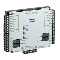
HID Aero™ X100 Installation Guide
PLT-04234, Rev. A.34
Powering
Trusted Identities
4. Input circuit wiring
Inputs are typically used for the following:
To monitor door position.
Request to exit.
Alarm contacts.
Input IN 1 to IN 4 circuits can be configured as
unsupervised or supervised and can use normally open
or normally closed contacts.
For a supervised circuit, add two 1KΩ, 1% resistors as
close to the sensor as possible.
Custom end of line (EOL) resistances may be configured
via the host software.
Note: The input circuit wiring configurations shown are
supported but may not be typical.
5. Relay circuit wiring
Four relays are provided for controlling door lock
mechanisms or alarm signaling.
When controlling the delivery of power to the door
strike, the NO (Normally Open) and C (Common) poles
are typically used.
When momentarily removing power to unlock the door,
as with a mag lock, the NC (Normally Closed) and C
(Common) poles are typically used.
Check with local building codes for proper egress door
installation.
CAUTION
Door lock mechanisms can generate feedback to the
relay circuit. This can cause damage and premature
failure of the relay, eecting the operation of the X100.
Use a diode to protect the relay. Use a wire of sucient
gauge to avoid voltage loss.
Diode selection:
Diode current rating: 1x strike current.
Diode breakdown voltage: 4x strike voltage.
For 12 V DC or 24 V DC strike, diode 1N4002
(100V/1A) typical.
- +
To DC power source
Diode
+
-
Fuse
DC Strike
RELAY 1 to
RELAY 4
Unsupervised circuit IN 1 to IN 4
Supervised circuit IN 1 to IN 4
1K,1%
1K,1%
 Loading...