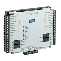
HID Aero™ X100 Installation Guide
PLT-04234, Rev. A.36
Powering
Trusted Identities
LED
POWER
ON SELF-TEST
NORMAL OPERATION
ONLINE ON then OFF
Heartbeat and Online status. Oine = 1 sec rate, 20% ON. Online encrypted comm .1 sec
ON, .1 sec OFF, .1 sec ON, .1 sec OFF, .1 sec ON, .1 sec OFF, .1 sec ON, .3 sec OFF. Waiting
for application download .1 sec ON, .1 sec OFF.
COMM ON then OFF RS-485 Comm status. Indicates communication activity on the SIO communication port.
BATT FAIL ON then OFF OFF = Inactive, ON = Active, Flash = Fault.*
AC FAIL ON then OFF OFF = Inactive, ON = Active, Flash = Fault.*
TAMPER ON then OFF OFF = Inactive, ON = Active, Flash = Fault.*
IN 1 ON then OFF OFF = Inactive, ON = Active, Flash = Fault.*
IN 2 ON then OFF OFF = Inactive, ON = Active, Flash = Fault.*
IN 3 ON then OFF OFF = Inactive, ON = Active, Flash = Fault.*
IN 4 ON then OFF OFF = Inactive, ON = Active, Flash = Fault.*
READER 1 ON then OFF
Wiegand or C&D mode = Flashes when data is received, either input.
OSDP mode = Flashes when transmitting data.
READER 2 ON then OFF
Wiegand or C&D mode = Flashes when data is received, either input.
OSDP mode = Flashes when transmitting data.
RELAY 1 OFF ON = Energized
RELAY 2 OFF ON = Energized
RELAY 3 OFF ON = Energized
RELAY 4 OFF ON = Energized
*If this input is defined, every three seconds the LED is pulsed to its opposite state for 0.1 seconds, otherwise,
the LED is OFF.
Status LEDs
7. Input power, cabinet tamper, and UPS fault input wiring
The X100 requires 12-24 V DC power. Connect power
with minimum of 18 AWG wire.
Grounding and Bonding: The DC ground or return wire
must be bonded to the Earth Ground of the building,
during installation.
Connect the power ground to earth ground in only ONE
LOCATION within the system. Multiple earth ground
connections may cause ground loop problems and is
not advised.
Observe POLARITY on 12-24 V DC input.
Connect the AC FAIL and BATT FAIL inputs to the
corresponding contacts provided on the power supply.
Connect the TAMPER input to a tamper switch on the
enclosure.
TAMPER, AC FAIL, and BATT FAIL connections are
identical to inputs IN 1 to IN 4 and can be configured
as unsupervised or supervised. See step 4. Input circuit
wiring.

 Loading...