EasyManua.ls Logo

HID Signo 40K - User Manual

HID Signo 40K
3 pages
Print Icon
To Next Page IconTo Next Page
Loading...
PLT-03704, Rev. A.3
hidglobal.com
An ASSA ABLOY Group brand
© 2019 - 2020 HID Global Corporation/ASSA ABLOY AB. All rights reserved. HID, the HID Brick logo, the Chain Design, HID Signo, HID Reader Manager, iCLASS,
and HID Mobile Access are trademarks or registered trademarks of HID Global, ASSA ABLOY AB, or its aliate(s) in the US and other countries and may not be
used without permission. All other trademarks, service marks, and product or service names are trademarks or registered trademarks of their respective owners.
Specifications
20 20K 40 40K
INPUT VOLTAGE (V DC) 12V DC
CURRENT
STANDBY AVG
1
60 mA 65 mA 65 mA 70 mA
MAX AVG
2
70 mA 75 mA 75 mA 80 mA
PEAK
3
250 mA 250 mA 250 mA 250 mA
OPERATING TEMPERATURE -30° F to 150° F (-35° C to 66° C)
CABLE LENGTH
Communication Lines
Wiegand = 500 ft - 18 AWG (152 m)
300 ft - 20 AWG (91 m)
RS-485 = Max bus length: 4,000 ft - 24 AWG (1,219 m)
Max length between nodes: 1,640 ft - 24 AWG (500m)
REGULATORY REF NUMBER 20 20K 40 40K
FREQUENCY BLE: 2.4–2.480 GHz, HF: 13.56 MHz, LF: 125 kHz
FCC IDS JQ6-SIGNO20 JQ6-SIGNO20K JQ6-SIGNO40 JQ6-SIGNO40K
IC IDS 2236B-SIGNO20 2236B-SIGNO20K 2236B-SIGNO40 2236B-SIGNO40K
1 Standby AVG - RMS current draw without a card in the RF field.
2 Maximum AVG - RMS current draw during continuous card reads. Not evaluated by UL.
3 Peak - highest instantaneous current draw during RF communication.
Supplied parts
HID Signo Reader (1)
Installation Guide (1)
Flat head/countersunk 0.138-20 x 1.5” self–tapping
screws (2) – for installing the reader directly to a wall
(no junction box)
Flat head/countersunk 0.138-32 x 0.375” machine
screws (3) – for Imperial (US) junction box installation
(2) and attaching the reader to the mounting plate (1)
Flat head/countersunk M3.5 x 12mm machine screws
(2) – for Metric (EU etc) junction box installation
Flat head/countersunk 0.138-32 x 0.375” security screw
(1) – alternative anti-tamper screw for attaching the
reader to the mounting plate
5-pin terminal connectors, terminal strip models only (2)
Recommended parts
(not supplied)
Cable, 5-10 conductor (Wiegand or Clock-and-Data),
4 conductor Twisted Pair Over-All Shield and UL
approved, Belden 3107A or equivalent (OSDP)
Certified LPS DC power supply
Metal or plastic junction box
Security tool HID 04-0001-03 (for anti-tamper screw)
Drill with various bits for mounting hardware
Mounting hardware
Reader spacer when mounting on or near metal
or metal junction boxes. Refer to the Reader and
Credentials How to Order Guide (PLT-02630) for
available options and part numbers
Junction box
HID® Signo™ Reader
13.56 MHZ/125 kHz/2.4 GHz Contactless and Keypad Readers
SRD Models: 20, 20K, 40, 40K
Installation Guide

Other manuals for HID Signo 40K

Question and Answer IconNeed help?

Do you have a question about the HID Signo 40K and is the answer not in the manual?

Summary

Optional Features

Mounting the Reader

Wiring the Reader

Overview

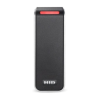
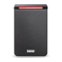
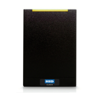
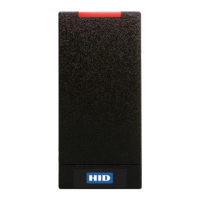
The HID Signo™ Reader is a versatile device designed for contactless access control, supporting multiple frequencies including 13.56 MHz, 125 kHz, and 2.4 GHz. These readers are available in various SRD models, specifically 20, 20K, 40, and 40K, catering to different installation and functional requirements.

Function Description

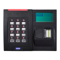
The primary function of the HID Signo Reader is to read credentials for access control systems. It supports multiple contactless technologies, allowing it to interact with a wide range of cards and mobile devices. The reader can be configured for various communication protocols, including Wiegand and RS-485 (OSDP), making it compatible with diverse access control panels. Keypad models (20K, 40K) integrate a keypad for PIN entry, providing an additional layer of security or an alternative authentication method.

The reader features several input/output lines for enhanced functionality. These include:

  • +VDC and Ground (RTN): For power supply to the reader.
  • Wiegand Data 1/Clock/RS485-A and Wiegand Data 0/Data/RS485-B:** These lines handle data communication with the access control panel. Depending on the configuration, they can transmit Wiegand data, clock signals, or RS-485 data for OSDP communication.
  • LED Input (GRN), LED Input (BLUE)*, and LED Input (RED): These inputs allow external control of the reader's LED indicators, providing visual feedback to the user.
  • Beeper Input: This input enables external control of the reader's audible beeper, offering auditory feedback.
  • Hold Input: This line can be configured to either buffer a card read (default) or disable card reading until released, providing control over when the reader processes credentials.
  • Tamper 1 (RLY1) and Tamper 2 (RLY2): These lines are part of the tamper detection feature. When the mounting plate is removed, the tamper circuit changes from normally closed to open, signaling a potential security breach. These lines are interchangeable and can be connected with the reader ground line to minimize cable core usage.
  • Drain (pigtail models only): This line is typically used for grounding or shielding purposes in pigtail versions of the reader.

For keypad models, the facility code configuration is a crucial aspect. When operating in 26-bit emulation, the facility code, followed by a '#' symbol, must be entered within five seconds of power-up. The facility code needs to be a three-digit number (e.g., '0-1-0-#' for facility code 10). If the entry is unsuccessful, the reader LED will display solid red, indicating a need to power-cycle and retry. HID Signo readers support facility codes between 1 and 255, with no default set. A successful facility code entry is indicated by the reader LED displaying violet, then solid red. If two short beeps occur after PIN entry, it signifies that the reader facility code is not configured, requiring a power-cycle and re-entry.

Usage Features

The HID Signo Reader is designed for ease of installation and flexible deployment. It comes with various mounting options and hardware to suit different environments:

  • Direct Wall Mounting: Flat head/countersunk 0.138-20 x 1.5" self-tapping screws are provided for direct installation onto a wall without a junction box.
  • Junction Box Installation: Flat head/countersunk 0.138-32 x 0.375" machine screws are supplied for Imperial (US) junction box installations, and M3.5 x 12mm machine screws for Metric (EU etc) junction boxes.
  • Mounting Plate: The reader attaches to a mounting plate, which simplifies installation and provides a secure base.
  • Pigtail and Terminal Strip Versions: Readers are available with either an 18" (0.46m) pigtail cable or a terminal strip for wiring connections, offering flexibility based on installation preferences and existing infrastructure.
  • Cable Recommendations: Specific cable types and lengths are recommended for optimal performance, such as Belden 3107A or equivalent for Wiegand/Clock-and-Data, and 24 AWG for RS-485, with maximum lengths specified to ensure reliable communication. For OSDP cable lengths exceeding 200 ft (61 m) or in environments with EMF interference, a 120Ω +/- 20 resistor across RS-485 termination ends is recommended.
  • Environmental Resilience: The reader is designed to operate in a wide temperature range, from -30°F to 150°F (-35°C to 66°C), making it suitable for various indoor and outdoor applications.
  • Aesthetics and Integration: The design of the Signo reader is intended for seamless integration into modern architectural environments.

Maintenance Features

While the HID Signo Reader is built for durability and long-term performance, certain considerations are important for its maintenance and optimal functioning:

  • Installation Integrity: Proper installation on a flat, stable surface is crucial to maintain the IP rating and ensure the tamper feature functions correctly. Failure to do so may compromise these aspects.
  • Spacer for Metal Surfaces: When mounting the reader on or near metal surfaces or metal junction boxes, a spacer is recommended. This helps optimize read performance by mitigating potential interference from the metal.
  • Use of Supplied Hardware: It is essential to use the screws supplied by HID for mounting. Using unapproved hardware can lead to incorrect fitting, potential damage to the reader or mounting plate, and may void warranty or support.
  • Electrostatic Discharge (ESD) Precautions: When handling the reader, especially during installation or wiring, observing precautions for electrostatic sensitive devices is important to prevent damage to internal components.
  • Wiring Accuracy: Correct wiring is paramount. Incorrect wiring can permanently damage the reader. Users should pay close attention to the wiring diagrams provided, especially when upgrading from older iCLASS® readers, as RS-485 wiring may have been reversed in previous models.
  • Tamper Feature: The tamper feature, enabled by default, provides a security mechanism by signaling if the reader is removed from its mounting plate. This allows for immediate detection of unauthorized tampering.
  • Firmware Updates: While not explicitly detailed as a user-maintenance feature, HID readers often support firmware updates to enhance functionality, improve security, or address potential issues. This is typically managed through specific tools or software provided by HID.
  • Troubleshooting Indicators: The reader's LED indicators provide visual cues for troubleshooting, such as a solid red LED indicating an unsuccessful facility code entry, guiding the user to corrective actions.

The HID Signo Reader is a robust and adaptable solution for modern access control, combining advanced technology with user-friendly installation and maintenance considerations.

HID Signo 40K Specifications

General IconGeneral
BrandHID
ModelSigno 40K
CategoryCard Reader
LanguageEnglish

Related product manuals