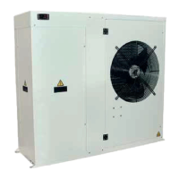
What to do if compressor 1 overload in HIdRos LSA/HP?
- UumoralesSep 13, 2025
Compressor 1 overload in your HIdRos Heat Pump indicates that the compressor input current is outside operation limits. Contact the Company to resolve this issue.
What to do if compressor 1 overload in HIdRos LSA/HP?
Compressor 1 overload in your HIdRos Heat Pump indicates that the compressor input current is outside operation limits. Contact the Company to resolve this issue.
General information about the manual's purpose, reproduction rights, and company policy.
Details the manual's objective to provide information for selection, installation, use, and maintenance.
Instructions for keeping the manual accessible and ensuring it accompanies the unit.
Recommendation to keep the manual updated and how to obtain latest information.
Guidance on using the manual, emphasizing the importance of symbols for safety.
Identifies potential risks associated with unit components and methods of injury, with precautions.
Explains safety symbols like BANNED, WARNING, and ACTION REQUIRED as per ISO 3864-2.
Details specific safety symbols for general risk, electrical hazard, moving parts, hot surfaces, and earth connection.
Specifies uses the machine is designed for and prohibits other uses due to potential risks.
Explains the unit rating plate and where to find key machine information.
Identifies refrigerant R410A, oil type, ecological information, and exposure limits.
Informs personnel about risks of handling potentially toxic substances and the need for proper training.
Advises on maintaining low atmospheric concentrations and ensuring adequate ventilation during operation.
Outlines steps for managing refrigerant leaks, including personal protection and ventilation.
Details toxicological effects of refrigerant exposure via inhalation, skin contact, eyes, and ingestion.
Provides first aid procedures for inhalation, skin contact, eye contact, ingestion, and further medical treatment.
Describes the unit's design for residential/commercial applications, its frame, refrigerant circuit, components, and control system.
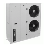
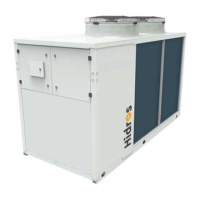
Lists control and protection devices like defrost thermostat, high pressure switch, and overload protection.
Details available versions such as reversible units and those with integrated hydraulic kits.
Describes various optional accessories like low noise versions, vibration dampers, and antifreeze heaters.
Presents a table showing the availability of accessories across different LSA/HP models.
Provides detailed technical specifications including cooling/heating capacity, power input, EER, COP, and sound data.
Presents graphs showing cooling capacity and input power correction factors based on water temperature.
Presents graphs showing heating capacity and input power correction factors based on ambient temperature.
Illustrates water pressure drops in the user heat exchanger for different models and water flow rates.
Shows available static pressure curves for the water pump across various models and water flow rates.
Defines the operational limits for water outlet temperature, ambient air temperature, and water flow rates.
Provides correction tables for operation with glycol, different temperature differences, and fouling factors.
Highlights essential safety rules, the need for trained personnel, and the correct use of safety symbols.
Emphasizes workplace cleanliness, lighting, ventilation, and the importance of following safety regulations.
Lists mandatory personal protective equipment (PPE) for operating and maintaining the unit.
Details procedures for inspecting the unit upon receipt and reporting any damages to the carrier.
Provides guidelines for storing units, recommending they remain in packaging and tools are transferred.
Advises on careful unpacking to prevent damage and proper disposal of packaging materials.
Offers recommendations for safe lifting and handling of units, emphasizing avoiding sudden movements and using appropriate methods.
Specifies site selection criteria and minimum clearances required around the unit for installation and maintenance.
Explains the installation of optional rubber vibration dampers to reduce vibration and noise transmission.
Details the installation and function of the serial interface card for MODBUS communication and remote monitoring.
Describes the installation of an optional drip tray with a self-heating antifreeze kit to manage condensate.
Outlines requirements for hydraulic pipework installation, including materials, insulation, and necessary components.
Specifies the required chemical characteristics for clean water used in the hydraulic system.
Lists the minimum water content required in the user hydraulic circuit for different unit models.
Provides technical data for the expansion vessel supplied with certain unit versions.
Illustrates factory-fitted and installer-supplied hydraulic components within the unit's circuits.
Details the step-by-step procedure for filling the hydraulic circuit and checking system pressure.
Explains the procedure for safely emptying the hydraulic installation, including fluid collection.
Provides crucial safety precautions for making electrical connections, including power supply and wiring.
Presents electrical data for standard units, referring to wiring diagrams for specifics and voltage tolerances.
Explains remote wiring connections for ON/OFF, summer/winter changeover, and general alarm.
Details specific connections for remote control panel and user circuit flow switch.
Shows the layout of the refrigerant circuit for the HP version with a detailed legend of components.
Lists essential checks for electric supply, connections, hydraulic system, and refrigerant circuit before starting.
Provides critical pre-start-up checks, warnings about using the main isolator, and pre-heating requirements.
Details the set points and differentials for various safety devices like thermostats and pressure switches.
Describes checks to perform during unit operation, including fan rotation and pump noise.
Explains how to check refrigerant charge using the sight glass and monitor operating temperatures.
Explains the control panel display icons and the functions of the keys for operation and programming.
Details the meaning of various icons displayed on the control panel.
Explains the functions of the 'MENU' and 'SET' keys and how to navigate menus and change set points.
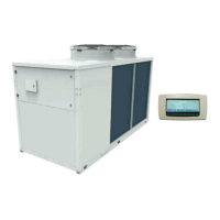
Describes the remote control panel, its display icons, and key functions for unit operation.
Lists and explains the icons visible on the remote control panel's display.
Details the functions of the 'MENU' and 'SET' keys on the remote panel for navigation and adjustments.
Provides instructions for installing the remote control panel, including panel cut-out dimensions and IP protection.
Instructions on how to power on the unit using the main switch and understanding the display.
Describes the procedure to start the unit in cooling mode, including safety delay and pump activation.
Describes the procedure to start the unit in heating mode, including safety delay and pump activation.
Instructions on how to stop the unit in cooling or heating mode, leading to stand-by.
Explains the stand-by mode, what the microprocessor controls, and visible indicators.
Guides on modifying operating parameters and set points, emphasizing stand-by mode for adjustments.
Lists adjustable parameters like heating/cooling set-points and password, with their limits and default values.
Explains how to access and view various parameters (e.g., alarm list, working hours) but not modify them.
Describes how to silence the buzzer for acoustic alarms.
Details how to reset alarms, distinguishing between resettable and non-resettable alarms.
Explains how to access and scroll through the unit's alarm history.
Provides general warnings for maintenance, including regulatory obligations, efficiency, failure prevention, and PPE.
Specifies that access to the unit must be restricted to authorized operators and technicians.
Outlines periodic checks to be performed by trained personnel to ensure correct unit operation.
Lists specific checks including safety devices, terminals, water leaks, flow switch, and heat exchanger condition.
Provides instructions for hydraulic circuit draining when the unit is switched off for a long period.
Details procedures for refrigerant recovery, leak detection using nitrogen, and precautions during repairs.
Outlines mandatory operations for decommissioning by authorized personnel, including refrigerant and oil recovery.
Specifies how to dismantle, sort, and dispose of unit components according to national regulations.
Explains the RAEE Directive requirements for electrical and electronic equipment disposal and recycling.
Provides guidance on fault finding, emphasizing resetting alarms only after removing the cause to prevent damage.
A table detailing alarm codes, descriptions, causes, and solutions for troubleshooting unit anomalies.
Presents dimensional drawings and specifications for LSA/HP models 06, 08, and 10.
Presents dimensional drawings and specifications for LSA/HP models 14 and 16.
Presents dimensional drawings and specifications for LSA/HP models 21, 26.
Presents dimensional drawings and specifications for LSA/HP models 31, 36, and 41.