0.065" (1.65mm)
0.050”
(1.3mm)
3/32" Hole3/32" Hole
Bridge
Brace
Saddle Slot
Guitar Top
Radius corner on both holes
Battery
Clips
The information presented here has been greatly enhanced over the years by listening
to the craftsmen who have installed countless numbers of these pickups. Thank you.
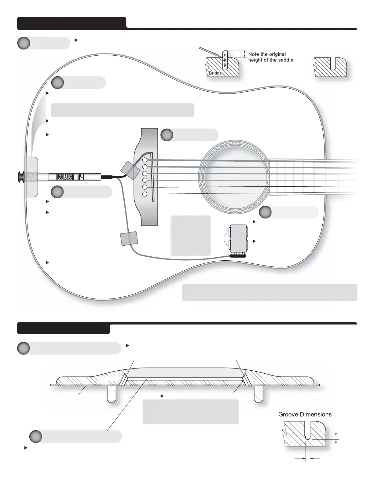
Remove the strings. Lightly scribe a line on the saddle or make a note of the saddle height. This is useful as a guide
when reseating the saddle at the original height.
Remove the saddle.
Drill a 17/32” (13.5mm) hole. Be sure to drill at 90º to end block.
Use a relieved bit to avoid wood tear out or end block splitting.
One way to drill a clean hole is to ream out the hole with a tapered reamer until
the drill bit goes 0.1” (2.5mm) into the hole (through the side). Then drill the hole
through the block. Note: Some people run the drill in reverse.
Thread with a 9/16”-12TPI tap (at 90º to end block).
The performance of the Highlander Pickup is optimized by embedding it in a groove in the bridge. This
‘couples’ the pickup to the sound board of the guitar capturing all of its energy, vitality and nuances.
Velcro®
Velcro®
Preparing the B
ri
dge
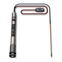
Pass the pickup and battery
snap through the end-pin hole.
Insert the preamp into the end-
pin hole, apply a little wood glue
(like Elmers') to the thread and
screw the preamp into the end-
pin hole by hand. Use a
chamois or rubber grip if
necessary. Do not use pliers or
anything similar as the strap nut
may be damaged.
Turn the wires inside the guitar to prevent twisting.
Untwist all the wires before continuing. Excessive
twisting of the black pickup cable may cause hum.
Thoroughly clean the area.
Push both clips onto a 9V
battery and attach the
connector.
Peel the backing off the
clips and press in place
on the back of the
guitar.
Prepare the bridge for the pickup.
See details of ‘Preparing the
Bridge’ below.
See details of the
pickup installation
on the next page.
Avoid a sharp bend. It is important that
the pickup is bent around a radius.
If a 90° 'hole angle' is unavoidable then
make the radius as large as possible.
Drill two 3/32” (2.5mm) holes at an angle as shown below. Being careful not to damage the Brace (or other
parts of the structure), try to get as close to a 45° 'hole angle' as possible.
Route a Groove for the pickup using a saddle router jig and router with a 1/16”
(0.0625”) (1.6mm) ball ended cutter. The groove should be 0.05" (1.3mm) deep.
The groove should extend from one 3/32" hole to the other, it should be smooth
and flat. Any irregularities in the groove may cause string imbalance.
The battery position shown in this diagram is one possible placement option. The battery can also be mounted on the neck block.
The actual position will depend on the type of instrument involved, and the needs of the musician using it.
Applying a light coat
of lacquer to the area
where the battery
clips are to be
attached significantly
improves adhesion.
Wait until the lacquer
is fully dry before
applying the clips.
Excess cable is held in place on the back of the guitar with Velcro®. Cables
should be loosely coiled. The Velcro® ensures the cable will not be pinched.
AVOID SHARP BENDS, KINKS or TWISTS IN THE CABLES.
End
Block
I
t
'
s
a
l
l
i
n
t
h
e
g
r
o
o
v
e
iP-1 INSTALLATION
The information and graphics contained in this document are the property of Highlander Musical Audio Products. Copying of any kind is prohibited, except for personal use only.
©
Highlander Musical Audio Products 1991-2009
Route the Pickup Groove
2b
Drill Two Holes for the Pickup
2a
Install Pickup
5
Install Battery
4
Install Preamp
3
Modification
2
Preparation
1
 Loading...