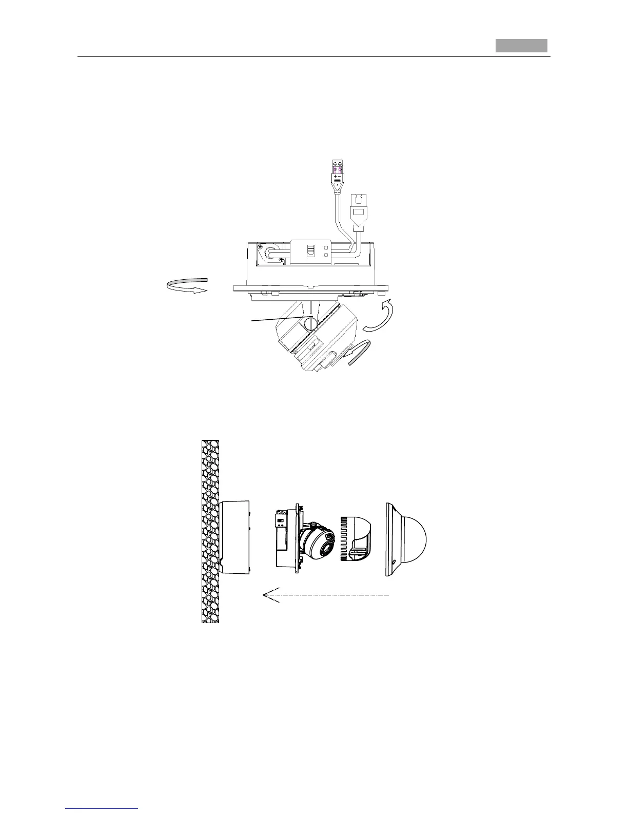
6. View the camera image over the network.
7. Loosen the lock screws to adjust the panning position and tilting position, and rotate the lens to get
the desired surveillance angle.
8. Fasten the lock screws.
Figure 3-51 Angle Adjusting
9. Reinstall the black liner and bubble to finish the installation.
Figure 3-52 Complete the Installation