Quick Start Guide of Network Video Recorder
14
Connector for RS-485 devices. T+ and T- pins connect to R+ and R-
pins of PTZ receiver respectively.
Connector for RS-232 devices.
D+, D- pin connects to Ta, Tb pin of controller. For cascading devices,
the first NVR’s D+, D- pin should be connected with the D+, D- pin of
the next NVR.
Connector for alarm input.
Connector for alarm output.
HDMI
TM
Output Extension
Board
16 HDMI
TM
video output connectors.
(provided for /H and /H/I models only)
Intel interface board for connecting to the x86 operating system host.
(provided for 96000NI-H series only)
DB9 connector for VGA output. Display local video output and menu.
100 ~ 240VAC power supply.
Intel Interface Board (for 96000NI-H series)
Intel Interface Board
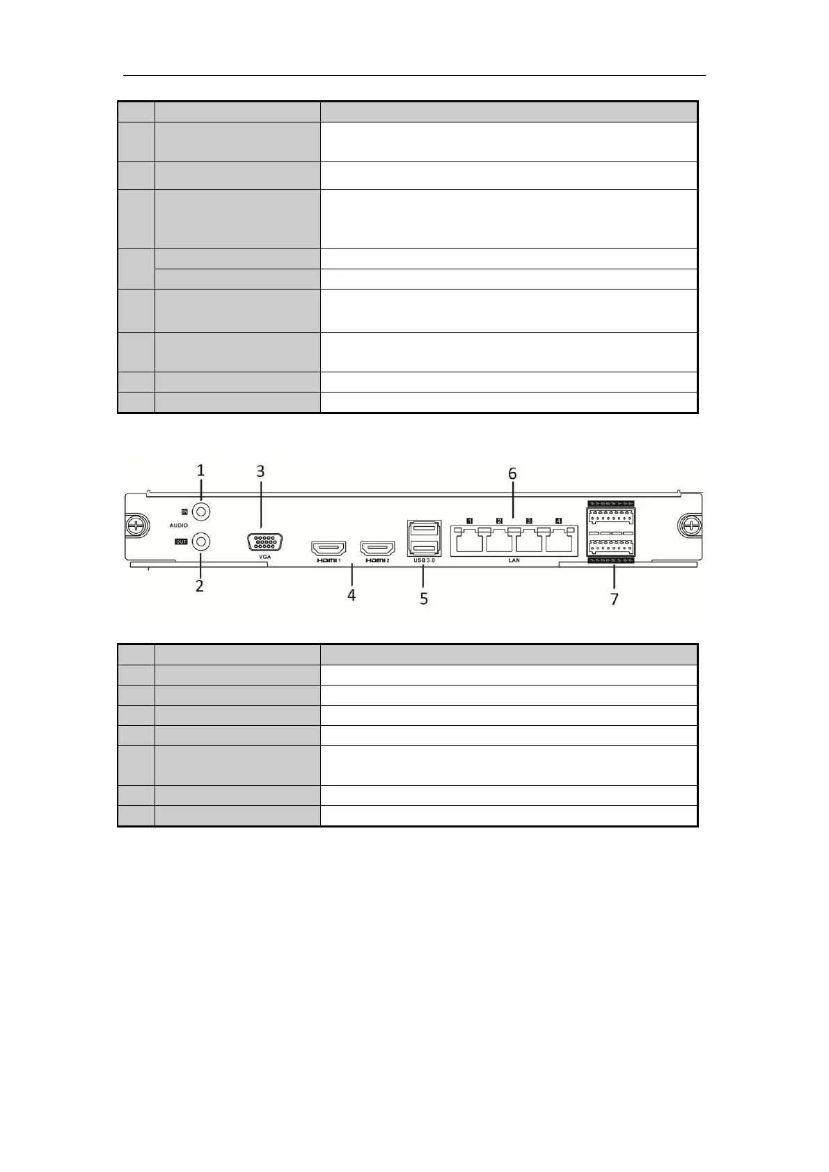
RCA connector for audio input.
RCA connector for audio output.
DB9 connector for VGA output. Display local video output and menu.
2 HDMI
TM
video output connectors.
Universal Serial Bus (USB) ports for additional devices such as USB
mouse and USB Hard Disk Drive (HDD).
4 LAN network interfaces.
 Loading...