1
2
3
3
AIN8
AIN7
AIN6
AIN5
AIN4
AIN3
AIN2
AIN1
GND
GND
RS485-
RS485+
COM2
NO2
COM1
NO1
Alarm TerminalsRS485/Relay Interface
122
1.5
Unit:mm
105.5
92
Rear Panel (without Interface)
Screw
Wall Mounng Plate Gang Box Wall
Lock Catch Lock Catch
Lock Catch Lock Catch
Hook
Hook
Hook
Hook
Rear Panel (without Interface)
Screw
Wall Mounng Plate Gang Box
Wall
Lock Catch Lock Catch
Lock Catch Lock Catch
Hook
Hook
Hook
Hook
Note: If you use the gang box (55 mm (width) × 101 mm (length) × 38.5 mm (depth)) to install, you should set the screws to le and right screw holes.
Note: If you use the gang box (75 mm (width) × 75 mm (length) × 46 mm (depth)) to install, you should set the screws to up and down screw holes.
Scan the QR code to get the
configuraon guide for detailed
informaon.
Scan the QR code to get the
operaon guide for detailed
informaon.
Hangzhou Hikvision Digital Technology CO.,Ltd. No.555 Qianmo Road, Binjiang District, Hangzhou 310052, China
1
2
3
7 8
54
9
10
11
6
12
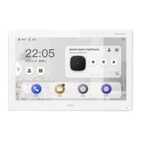
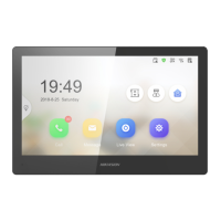
DS-KH9510-WTE1
Android Indoor Staon
Diagram References
ENGLISH
Refer to Video Intercom Network Indoor Staon Configuraon Guide (scan the QR code) for details.
Refer to Video Intercom Network Indoor Staon Operaon Guide (scan the QR code) for details.
UD19191B
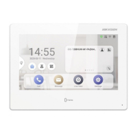
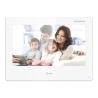
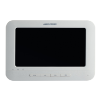
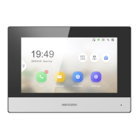
Appearance
Installaon
Before you begin:
Wall Mounng with Gang Box
1
3
Terminal
2
Screen Microphone Unlock Buon1 2 3 4
5 6 7
Make sure the device in the package is in good condion and all the assembly parts are included.
The power supply of the indoor staon is 12 VDC. Make sure your power supply matches your indoor
staon.
Make sure all related equipments are power-off during the installaon.
Check the product specificaon for the installaon environment.
The wall mounng plate and the gang box are required to install the indoor staon onto the wall.
There are 2 sizes of the gang boxes adapted to the device.
Size 1: 75 mm (width) × 75 mm (length) × 46 mm (depth).
Size 2: 55 mm (width) × 101 mm (length) × 38.5 mm (depth).
1. Cave a hole in the wall.
Note: The suggested dimension of the installaon hole should be larger than the gang box.
2. Insert a gang box to the hole chiseled on the wall.
3. Fix the wall mounng plate to the gang box with 2 screws.
Notes:
If you install the device with a gang box (75 mm (width) × 75 mm (length) × 46 mm (depth)), the upper and lower holes
will be applies.
If you install the device with a gang box (55 mm (width) × 101 mm (length) × 38.5 mm (depth)), the upper and lower
holes will be applies.
4. Hook the indoor staon to the wall mounng plate ghtly by inserng the plate hooks into the slots on
the rear panel of the indoor staon, during which the lock catch will be locked automacally.
Mounng Accessories
RS-485/Relay Interface
Power Supply Interface
Alarm Terminals
9 10 Reserved 11 TAMPERLoudspeaker
AIN1: Alarm Input 1
AIN2: Alarm Input 2
AIN3: Alarm Input 3
AIN4: Alarm Input 4
NO1/NO2: Normally Open
COM1/COM2: Common Interface
RS485-/RS485+: RS-485 Communicaon Interface
AIN5: Alarm Input 5
AIN6: Alarm Input 6
AIN7: Alarm Input 7
AIN8: Alarm Input 8
GND: Grounding
Debugging Port 8 microUSB Interface
Note: The appearance of the device varies according to different models. Refers to the actual device for detailed
informaon.
Note: For Wiring descripon, refers to the User Manual.
Acvate Indoor Staon
Geng Started
4
1. Choose Language and tap Next.
2. Set network parameters and tap Next.
- Edit Local IP, Subnet Mask and Gateway parameters.
- Enable DHCP, the device will get network parameters automacally.
3. Configure the indoor staon and tap Next.
a. Select Indoor Staon Type.
b. Edit Floor and Room No.
4. Linked related devices and tap Next. If the device and the indoor staon are in the
same LAN, the device will be displayed in the list. Tap the device or enter the serial No.
to link.
a. Tap the door staon in the list to link.
b. Tap the sengs icon to pop up the Network Sengs page.
c. Edit the network parameters of the door staon manually or enable DHCP to get
the network parameters automacally.
d. Oponal: Enable Synchronize Language to synchronize the Language of door
staon with indoor staon.
e. Tap OK to save the sengs.
5. Tap Finish to save the sengs.
1. Power on the device. It will enter the acvaon page automacally.
2. Create a password and confirm it.
3. Tap OK to acvate the indoor staon.
You are required to acvate the device first by seng a strong password before
you can use the device.
1
Quick Configuraon
2
The power supply must conform to LPS. The recommended adaptor models and
manufacturers are shown as below. Use the aached adaptor, and do not change the
adaptor randomly.
Model Current Manufacturer Standard
MSA-C1500IC12.0-18P -US 1.5 A MOSO POWER SUPPLY TECHNOLOGY CO.,LTD PG
TS-A018-120015AD 1.5 A SHENZHEN TRANSIN TECHNOLOGIES CO.,LTD PG
12 Network Interface