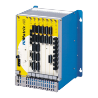
The device described in this manual is the HIMatrix DIO 24/16 01, a safety-related controller module designed for the modular F60 HIMatrix system. It functions as a plug-in module, providing 24 digital input channels and 16 digital output channels, all galvanically isolated from the I/O bus. The status of these input and output signals is indicated by LEDs located on the front plate next to the terminal plugs.
Function Description
The DIO 24/16 01 module is equipped with safety-related inputs and outputs, certified by TÜV for safety-related applications up to SIL 3 (IEC 61508, IEC 61511, IEC 62061), Cat. 4 (EN 954-1), and PL e (EN ISO 13849-1).
Safety-Related Digital Inputs:
Each group of 8 inputs is supplied with a common, short-circuit-proof LS+ on the clamps. In the event of a fault detected on a digital input, the module processes a low level according to the de-energized to trip principle, and the FAULT LED activates. The user program must consider the corresponding error code, which allows for configuring additional fault reactions.
Safety-Related Digital Outputs:
Each group of 8 outputs is provided with a connector on the clamps for a common ground. If an output channel is overloaded, it switches off for ten seconds until the overload is no longer present. If the module's total output load exceeds 8 A, all outputs switch off for 10 seconds, followed by a new test. In case of a faulty signal on a digital output or a module fault, the affected output(s) are set to the safe (de-energized) state using safety switches, and the FAULT LED activates. Error codes enable user-defined fault reactions in the program.
Line Control:
Digital outputs DO 1 through DO 8 can be used for line control, monitoring digital inputs of the same or other modules (e.g., DI 32 01) for short-circuits and open-circuits. This is particularly useful for applications like EMERGENCY STOP buttons complying with Cat. 4. These outputs are pulsed and connected to safety-related digital inputs, effectively functioning as pulsed outputs. It is crucial to note that pulsed outputs must not be used as safety-related outputs. Line control parameters are configured via system parameters, as detailed in the HIMatrix Engineering Manual.
Important Technical Specifications
General:
- Operating Voltage: 24 VDC, -15% to +20%, with Wss ≤ 15%, provided by a power supply unit with safe isolation (IEC 61131-2 requirements).
- Operating Data: 24 VDC / 380 mA, 3.3 VDC / 150 mA.
- Ambient Temperature: 0 °C to +60 °C.
- Storage Temperature: -40 °C to +85 °C.
- Space Requirement: 6 RU, 4 HP.
- Weight: 260 g.
- Protection Class: III (IEC/EN 61131-2).
- Pollution Degree: II (IEC/EN 61131-2).
- Altitude: < 2000 m.
- Housing Standard: IP20.
Digital Inputs:
- Number of Inputs: 24 (galvanically isolated).
- Input Voltage: Nom. 24 VDC (High level: 10 V to 30 V, Low level: max. 5 V).
- Input Current: High level: 2 mA at 10 V, 5 mA at 24 V; Low level: 1 mA at 5 V.
- Switching Point: Typ. 7.5 V.
- Supply: 3 x 20 V / 100 mA (at 24 V), short-circuit-proof.
Digital Outputs:
- Number of Outputs: 16 (galvanically isolated).
- Output Voltage: 18.4 VDC to 26.8 VDC.
- Internal Voltage Drop: Max. 2 W at 2 A.
- Output Current (at 30 °C): 2 A each channel, max. 8 A each module, permanently short-circuit-proof.
- Minimum Load: 2 mA for each channel.
- Leakage Current (low level): Max. 1 mA at 2 V.
Usage Features
Installation and Mounting:
The module is designed for insertion into slots 3-8 of the F60 subrack. Slots 1 and 2 are reserved for the power supply and CPU modules.
- Mounting: Insert the module into the guiding rails, apply pressure until it snaps into the backplane socket, and secure with screws.
- Removal: Unplug connectors, release locking screws, and loosen the module using the handle.
- Cabling: Shielded cables are not mandatory but improve EMC conditions. The cable shielding diameter should not exceed 12 mm for proper connection to the F60 earth grid. 9-pole connectors with numbered terminals are used for inputs and outputs, matching the terminal pins on the front plate to prevent improper connections.
Surges on Digital Inputs:
Due to the HIMatrix system's short cycle time, surge pulses (EN 61000-4-5) can be read as short-term high levels. To ensure proper operation in such environments:
- Install shielded input wires.
- Activate noise blanking, requiring a signal to be present for at least two cycles before evaluation. Activating noise blanking increases the system's response time.
Protective measures against overvoltage, lightning, earth grounding, and plant wiring must comply with relevant standards and the System Manual (HI 800 141 or HI 800 191).
Configuration:
The DIO 24/16 01 can be configured using either SILworX (for operating system versions 7 and beyond) or ELOP II Factory (for versions prior to 7). Projects created with one tool cannot be edited with the other.
- Module Slots: The module slots are numbered differently in SILworX and ELOP II Factory.
- SILworX Configuration: In the Hardware Editor, I/O modules are dragged to available slots. Double-clicking a module opens the Detail View, where global variables from the user program are assigned to system parameters.
- ELOP II Factory Configuration: Signals defined in the Signal Editor are assigned to individual channels.
Operation and Diagnosis:
The module operates within a HIMatrix base plate without requiring specific monitoring.
- Handling: No specific handling is required during operation.
- Diagnosis: Initial diagnosis is performed by evaluating the module's LEDs (RUN, ERR, I/O LEDs). The device's diagnostic history can also be accessed via the programming tool.
Mounting in Zone 2 (EC Directive 94/9/EC, ATEX):
The device is suitable for mounting in Zone 2, subject to special conditions:
- Must be mounted in an enclosure meeting EN 60079-15 requirements (at least IP 54, EN 60529). The enclosure must bear a label stating: "Work is only permitted in the de-energized state" (with an exception if a potentially explosive atmosphere is precluded).
- The enclosure must safely dissipate generated heat. Power dissipation of each module is 25 W at maximum output load.
- Must be supplied with 24 VDC from a power supply unit with safe isolation (PELV or SELV type).
- Compliance with specific sections of DIN EN 60079-15 and DIN EN 60079-14 regarding design, terminals, cabling, air/creeping distances, connectors, and equipment for Zone 2 use.
The module itself carries a label indicating its suitability for Ex II 3G EEx nA II T4 X conditions, with an ambient temperature range of 0 °C ≤ Ta ≤ 60 °C, and explicitly stating that "Special conditions X must be regarded!"
Maintenance Features
General Maintenance:
No maintenance is required during normal operation. If a module fails, it must be replaced with a faultless device of the same type or an approved replacement model. Only the manufacturer is authorized to repair the device.
- Module Replacement: Modules can only be replaced when the power is switched off. They must not be removed or inserted during operation. The instructions for mounting and removing modules (Chapter 4.1.1) must be followed.
- Fault Reaction: The module activates the FAULT LED upon detecting a fault on an input or output, and the user program processes a low level for inputs or sets outputs to a safe state.
Processor Module Maintenance (Rarely Required):
- Loading the Operating System: HIMA recommends loading current operating system versions during system downtimes. The controller must be in STOP mode before loading. Refer to the programming tool documentation for details.
- Proof Test: HIMatrix modules should be tested every 10 years. Refer to the Safety Manual (HI 800 003) for more information.
Decommissioning:
To decommission the module, remove the supply voltage, then pull out the pluggable screw terminal connector blocks for inputs and outputs and the Ethernet cables.
Transport and Disposal:
- Transport: HIMatrix components must be transported in their original product packaging to prevent mechanical damage and protect against electrostatic discharge. The product packaging alone is not suitable for transmission.
- Disposal: Industrial customers are responsible for correctly disposing of decommissioned HIMatrix hardware. A disposal agreement can be arranged with HIMA upon request. All materials must be disposed of in an ecologically sound manner.