Do you have a question about the HIMA HIMax X-DI 32 02 and is the answer not in the manual?
Details the manual's organization and how to effectively use its content.
Identifies the intended readers and the required technical knowledge for this document.
Explains the typographical conventions and symbols used for clarity in the manual.
Highlights critical safety information and warnings to prevent hazards and ensure safe operation.
Provides useful hints and best practices for operating the module effectively.
Defines the specific applications and purposes for which the HIMax module is designed.
Specifies the conditions like temperature, humidity, and altitude for proper module operation.
Outlines necessary precautions to prevent damage from electrostatic discharge during handling.
Discusses potential risks that remain even after safety measures are implemented.
Lists general safety measures and required personal protective equipment for safe work.
Provides guidance on actions to take in case of system failure or emergencies.
Describes the module's role in safety-related functions and its compliance with safety standards.
Explains how the module behaves and what happens when a fault is detected.
Lists the components included with the module and what is not.
Details the information provided on the module's identification label.
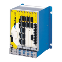
Covers the physical installation and integration of the module into the system.
Illustrates the internal structure and functional connections of the module.
Shows the location and types of LED indicators on the module for status display.
Explains the meaning of LEDs indicating the module's operational status (Run, Error, Stop, Init).
Describes the LEDs that signal the status of the system bus connection.
Details the LEDs that indicate the status of individual digital inputs/outputs.
Lists the technical specifications, electrical data, and physical dimensions of the module.
Introduces the accessory connector boards used for module integration and field wiring.
Explains the physical coding mechanism to ensure correct module-to-board pairing.
Specifies the coding positions for X-CB 005 series connector boards.
Presents connector boards utilizing screw terminals for field connections.
Provides a detailed mapping of pins to signals for screw terminal connector boards.
Showcases connector boards designed for use with cable plugs for field connections.
Details the pin configuration for system cable plugs connecting to connector boards.
Explains how to set up redundant connector boards across multiple base plates.
Specifies the pinout for the X-CB 005 05 connector board variant.
Describes the system cables used for connecting modules to field termination assemblies.
Details the specifications and usage of the X-CA 002 system cable.
Outlines the specifications and application of the X-CA 009 system cable.
Explains the coding mechanism of cable plugs for proper connection.
Instructions for physically installing the module into the base plate and securing it.
Guidance on how to properly handle digital inputs that are not actively used.
Step-by-step procedure for installing and detaching the module from its slot.
Provides detailed steps for installing and removing the HIMax module from the base plate.
Guides users through the process of setting up the module using the SILworX software.
Details the parameters and statuses available in the 'Module' tab of the SILworX Hardware Editor.
Explains the parameters and statuses for the DI32_02 I/O submodule in SILworX.
Describes the parameters and statuses for individual channels within the DI32_02 submodule.
Lists and explains the bit-coded status values for the submodule.
Details the diagnostic codes and their meanings for troubleshooting.
Presents different valid methods for wiring the module in safety-related applications.
Illustrates how to connect proximity switches and wired contact makers to the module.
Describes the connection procedure using a field termination assembly.
Explains the setup for redundant module connections using separate base plates.
Provides information on the direct handling and interaction with the module.
Explains how to interpret module states using LEDs and SILworX for diagnosing issues.
Outlines the procedures for maintaining the module's operational integrity.
Details the process for updating or loading the module's operating system.
Specifies the requirements and frequency for performing proof tests on HIMax modules.
Defines technical terms and acronyms used throughout the manual.
Lists all figures included in the document with their corresponding page numbers.
Provides a reference to all tables within the manual and their locations.
An alphabetical listing of topics and keywords with page references for quick lookup.
| Brand | HIMA |
|---|---|
| Model | HIMax X-DI 32 02 |
| Category | Control Unit |
| Language | English |