Do you have a question about the HIMA HIMax X-AI 32 02 and is the answer not in the manual?
Outlines the manual's structure and references to other documents.
Identifies the intended readers for this manual.
Explains the use of fonts, colors, and symbols for readability.
Details the structure and meaning of safety notes to avoid hazards.
Describes the presentation of useful tips and tricks for operation.
Specifies the purpose of HIMax components in safety-related systems.
Lists operational parameters like temperature, humidity, and altitude.
Outlines necessary precautions to prevent electrostatic discharge damage.
Discusses potential risks arising from faults in engineering, program, or wiring.
Emphasizes observing local safety rules and using protective equipment.
Explains the system's safe state upon controller failure during emergencies.
Details the module's safety function performance and SIL rating.
Describes how the module adopts a safe state and signals faults.
Lists included items and specifies that connector boards are separate.
Explains the information provided on the product's type label.
Describes the module's analog inputs, isolation, and system bus connection.
Illustrates the module's internal structure and connections.
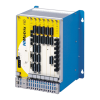
Shows the location and types of LED indicators on the module front.
Details the meaning of Run, Error, Stop, and Init LEDs.
Explains the LEDs indicating system bus connection status (A, B).
Describes the LEDs for channel status and field faults.
Provides technical specifications including supply voltage, temperature, and dimensions.
Lists available connector boards for connecting modules to the field.
Explains mechanical coding to ensure correct module-connector pairing.
Details coding positions for specific X-CB 008 connector boards.
Shows pin assignments for mono, redundant, and three-fold screw terminal boards.
Provides detailed pin-to-signal mapping for screw terminals.
Illustrates pin assignments for mono, redundant, and three-fold cable plug boards.
Details pin assignments for system cable plugs based on DIN 47100.
Explains how to achieve redundancy using two system base plates.
Specifies pin assignments for the X-CB 008 05 connector board variant.
Describes system cables used to wire connector boards to field termination assemblies.
Details the specifications of the X-CA 005 system cable.
Provides specifications for the X-CA 009 system cable.
Explains the coding mechanism of cable plugs for compatibility.
Provides general points to observe when mounting the module.
Gives guidance on terminating or leaving unused inputs open.
Details the procedures for installing and uninstalling the HIMax module.
Step-by-step instructions for installing a connector board.
Detailed guide for mounting and removing the module from the base plate.
Explains the SOE function, its support, and event composition.
Overviews module configuration using the SILworX programming tool.
Details the statuses and parameters available in the Module tab.
Explains statuses and parameters in the I/O Submodule Al32_02 tab.
Describes channel-specific parameters and statuses for analog inputs.
Provides coding for various submodule status codes.
Explains coding for diagnostic status values and fault information.
Describes permitted wiring configurations for safety-related applications.
General guide for wiring analog inputs using connector boards.
Details wiring transmitters using the X-FTA 002 01 assembly.
Explains redundant connection setups with two base plates.
Describes methods for EX-protection using Zener barriers.
Details EX-protection implementation using power supply isolators.
Explains HART communication and its impact on analog measurements.
Notes that direct handling is not foreseen and operation is via PADT.
Explains how to check module state using LEDs and SILworX.
Outlines general measures for maintaining the module.
Instructions for updating the module's operating system.
Specifies the required proof test interval for HIMax modules.
Describes the process of removing the module from its base plate.
Provides guidelines for safely transporting HIMax components in packaging.
Outlines responsibilities for correct disposal of HIMax hardware.
Defines technical terms and abbreviations used in the manual.
Lists all figures and their corresponding page numbers.
Lists all tables and their corresponding page numbers.
Provides an alphabetical index of keywords and topics.
| Brand | HIMA |
|---|---|
| Model | HIMax X-AI 32 02 |
| Category | Control Unit |
| Language | English |