3 Product Description X-AI 32 02
Page 12 of 60 HI 801 055 E Rev. 4.00
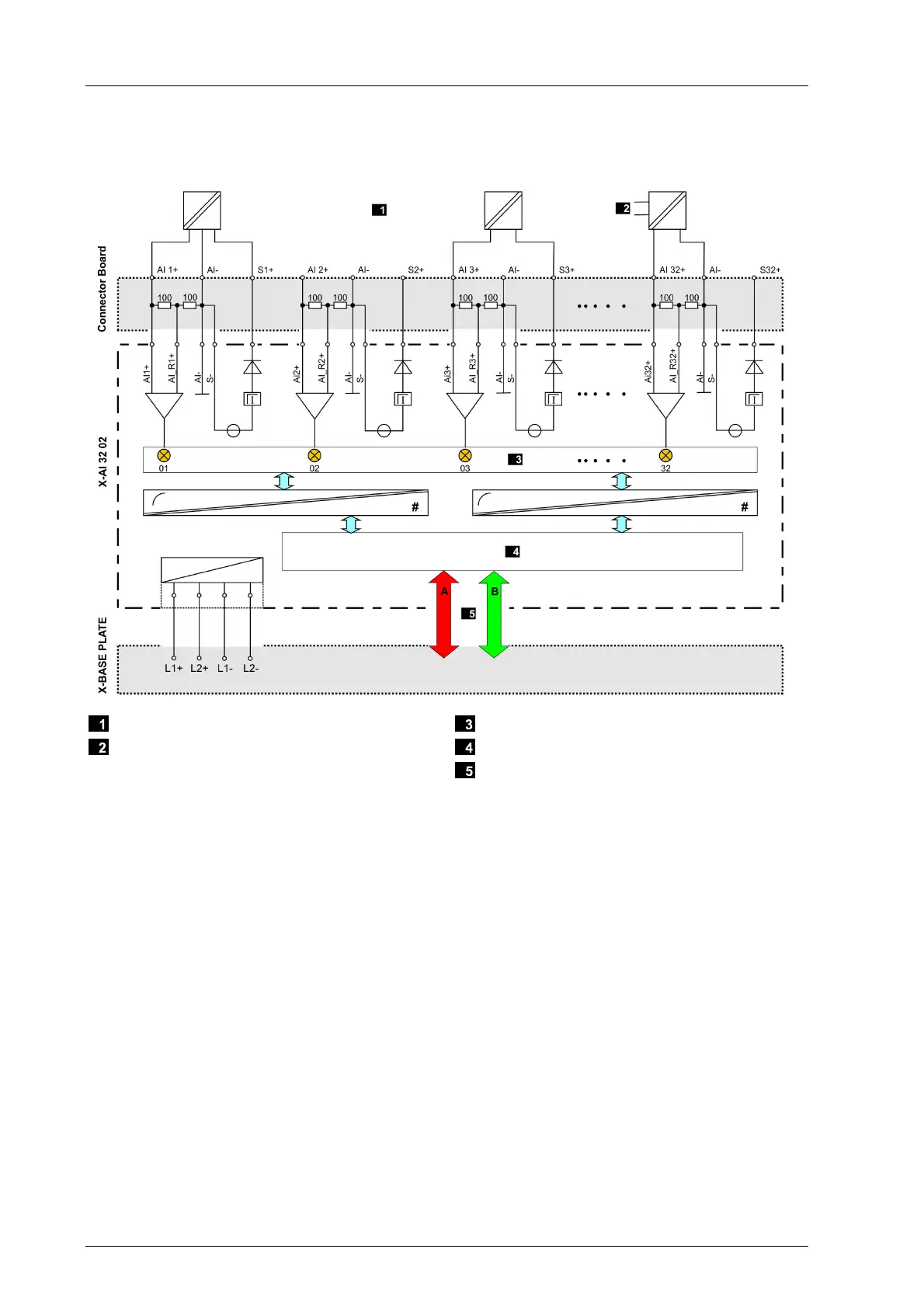
3.4.1 Block Diagram
The following block diagram illustrates the structure of the module.
Field Side: Transmitter and Wired Contacts
External Transmitter Supply
Interface
Safety-Related Processor System
System Busses
Figure 2: Block Diagram

 Loading...

