Do you have a question about the Hino Motors W04D and is the answer not in the manual?
Safety precautions for engine maintenance and operation to prevent personal injury and property damage.
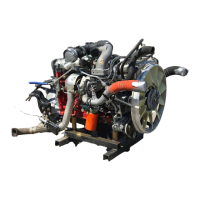
Detailed technical specifications for the HINO W04D diesel engine.
Technical data and specifications for the engine models.
Guidelines for determining when engine overhaul is necessary.
Diagram and specifications for the engine's lubricating system.
Conditions that indicate when a turbocharger overhaul is needed.
Procedures for disassembling, cleaning, and assembling the turbocharger.
Detailed procedures for disassembling and assembling the injection pump.
Procedures for adjusting injection timing, interval, and volume.
Diagram and labels for governor components for overhaul.
Diagnosing and resolving common starter faults like no crank or slow crank.
Procedures for adjusting the governor for the W04D engine model.
Specific governor adjustment procedures for the W04C-TI model.
Specific governor adjustment procedures for the W04C-T model.
| Engine Model | W04D |
|---|---|
| Number of cylinders | 4 |
| Displacement | 4.009 L |
| Bore x Stroke | 104 mm x 118 mm |
| Fuel System | Direct Injection |