5 78
6
• This function automatically switches to the power save state
when 30 minutes have elapsed since the last operation.
• The auto power save function is activated automatically
when the power is turned on. To restore from the auto power
save state, turn the function switch to the OFF position once.
To Disable Auto Power Save
1.Move the function switch from the OFF position to the
(continuity check) position before all display segments
appear.
2.While all display segments appear (about one second), move
the function switch from to . APS
OFF is displayed,
and the Auto Power Save function is disabled. Turning the
function switch momentarily OFF and then back on reacti-
vates Auto Power Save.
When measuring a DC voltage [ V], AC voltage [ V], or re-
sistance [], the measurement range is automatically set to the
most appropriate range. Manual range setting is not possible.
When the input exceeds the measurement range, "OF" is dis-
played.
Handling the Sleeve
]
Pre-Operation inspection
To avoid the possibility of electric shock or incorrect measure-
ment, check the following items before using the instrument.
If the operation check reveals any abnormalities, stop the check
immediately and do not use the instrument.
• For voltage measurement, short the test leads and check that
0 V is displayed.
• For Measuring Resistance or Continuity Check, short the test
leads and check that 0 is displayed.
• Measure a test item with a known value (battery, AC supply,
resistor, etc.) to confirm that the known value can be dis-
played.
1.Set the function switch to V.
2.Connect the test leads to the object to be measured.
3.Read the display.
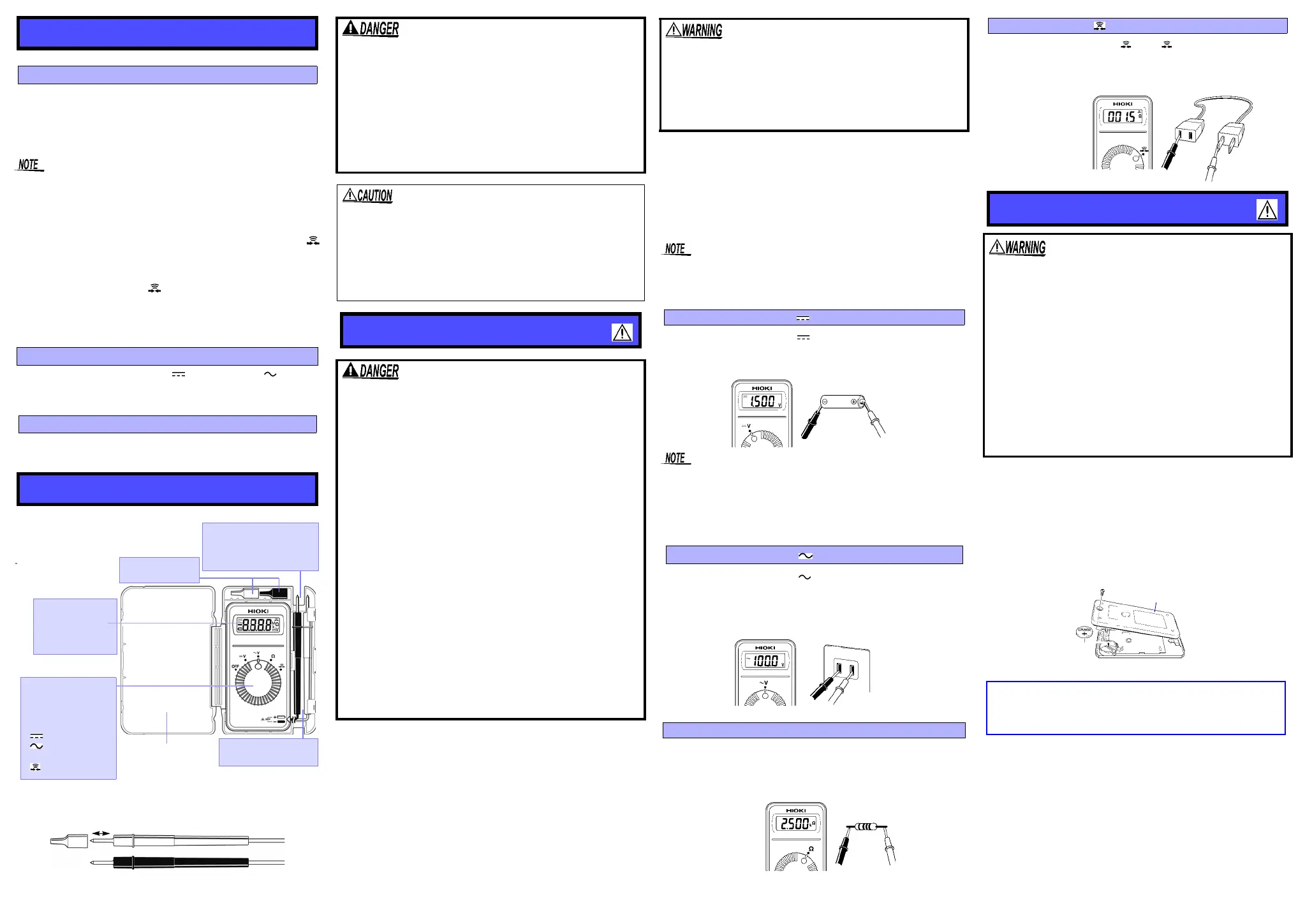
1.Set the function switch to V.
2.Connect the test leads to the object to be measured. When
measuring AC voltage, the polarity of leads can be ignored.
3.Read the display.
1.Set the function switch to .
2.Connect the test leads to the object to be measured.
3.Read the display.
1.Set the function switch to . The indication appears.
2.Connect the test leads to the object to be measured.
3.Conductivity is good when the buzzer sounds.
1.Remove the test leads from the test item, and power the
instrument off.
2.Remove the instrument from the case, and remove the
screws on the rear panel.
3.Remove the used battery.
4.Being careful about the polarity, insert the new battery
(CR2032) of the specified type.
5.Replace the rear panel and fasten the screws.
Functions
Auto Power Save Function
To avoid battery depletion, turn the function selector OFF after
use (the Auto Power Save feature consumes a small amount of
current).
Auto-range Function
Overflow Display
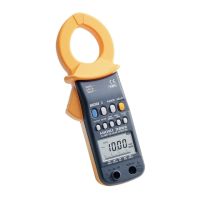
Names and Functions of Parts
Test lead
Red (+) / Black (-)
Connect the test leads to the
object to be measured.
Display
• Measurement value
• Units
• Symbols
• Decimal point
Function switch
• [OFF] Power Off
(
Power is turned ON in
any position other than
OFF.
)
• [ V]DC voltage
• [ V] AC voltage
• []Resistance
• [ ]Continuity check
Test lead be stored here.
Wind wire around case.
Carrying Case
Sleeves
Can be stored here.
Removable sleeves can be attached to the metal
pins at the ends of the test leads. To prevent a short
circuit accident, be sure to use the test leads with
the sleeves attached when performing measure-
ments in the CAT III measurement category. Remove
the sleeves from the test leads when performing
measurements in the CAT II measurement category.
For details on measurement categories, see "Mea-
surement categories" in the instruction manual.
• The tips of the metal pins are sharp, so take care not to injure
yourself.
• When performing measurements with the sleeves attached,
be careful to avoid damaging the sleeves.
• If the sleeves are inadvertently removed during measure-
ment, be especially careful in handling the test leads to avoid
electric shock.
Measurement Method
Observe the following precautions to avoid electric
shock.
• Always verify the appropriate setting of the function
selector before connecting the test leads. Disconnect
the test leads from the measurement object before
switching the function selector.
• Never apply voltage to the test leads when the Resis-
tance measurement, Continuity check functions are
selected. Doing so may damage the instrument and
result in personal injury. To avoid electrical accidents,
remove power from the circuit before measuring.
• The maximum input voltage is 500 V DC/ACrms or 3 x
10
6
•V/Hz. Attempting to measure voltage in excess of
the maximum input could destroy the instrument and
result in personal injury or death.
• To avoid electrical shock, be careful to avoid shorting
live lines with the test leads.
• For safety, test lead connections must always be
made at the secondary side of a circuit breaker.
• The maximum rated voltage between input terminals
and ground is CAT III (300 V), CAT II (600 V). Attempt-
ing to measure voltages exceeding 450 V with respect
to ground could damage the instrument and result in
personal injury.
To prevent an electric shock accident, confirm that
the white portion (insulation layer) inside the cable is
not exposed. If a color inside the cable is exposed, do
not use the cable. Using the instrument in such con-
ditions could cause an electric shock, so contact
your dealer or Hioki representative for repair.
Periodic calibration and inspecton is necessary in order to en-
sure that this instrument operates according to its product spec-
ifications.
Measuring DC Voltage [ V]
• Connecting the leads of negative and positive side oppositely,
"-" is displayed.
• The displayed value may sometimes fluctuate due to induc-
tion potential even when no power is supplied. This, however,
is not a malfunction.
Measuring AC Voltage [ V]
Measuring Resistance []
Continuity Check [ ]
Replacing Battery
• To avoid electric shock when replacing the batteries,
first disconnect the test leads from the object to be
measured. After replacing the batteries, replace the
cover and screws before using the instrument.
• Be sure to insert them with the correct polarity. Other-
wise, poor performance or damage from battery leak-
age could result. Replace batteries only with the
specified type.
• Battery may explode if mistreated. Do not short-circuit,
recharge, disassemble or dispose of in fire.
• Handle and dispose of batteries in accordance with
local regulations.
• Keep batteries away from children to prevent acciden-
tal swallowing.
CALIFORNIA, USA ONLY
This product contains a CR Coin Lithium Battery which contains
Perchlorate Material - special handling may apply.
See www.dtsc.ca.gov/hazardouswaste/perchlorate

 Loading...