EasyManua.ls Logo

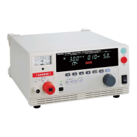
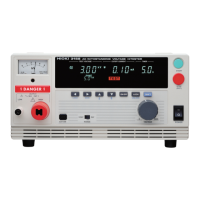
Hioki 3159 User Manual

Hioki 3159
188 pages
To Next Page IconTo Next Page
Page #1 background imageLoading...
Page #1 background image
INSTRUCTION MANUAL
3159
INSULATION/
WITHSTANDING
HiTESTER

Table of Contents

Other manuals for Hioki 3159

Questions and Answers:

Hioki 3159 Specifications

General IconGeneral
TypeInsulation Resistance Tester
Measurement FunctionsInsulation Resistance, Resistance
DisplayLCD
Test Voltage250 V, 500 V, 1000 V
Test Current1 mA max.
Display Digits3.5 digits
Output Frequency50 Hz/60 Hz
Power SupplyBattery
Weight (Alternative)Approx. 2.5 kg (including batteries)

Summary

Safety Notes

Notes on Use

DANGER Warnings

Critical warnings about electric shock and high voltages associated with product use.

General Warnings

Important warnings regarding water, grounding, cable handling, and fuse replacement.

Chapter 1 Overview

1.1 Product Introduction

Overview of the HIOKI 3159 HiTESTER features and capabilities.

1.2 Names and Functions of Parts

Identifies and describes components on the front and rear panels, leads, and accessories.

Chapter 2 Testing Arrangements

2.1 Connecting the Protective Ground Terminal

Instructions for properly connecting the protective ground terminal for safety.

2.4 Powering On and Off the Unit

Procedures for safely powering the HiTESTER unit on and off, including warm-up.

2.5 Connecting the 9615 H.V. TEST LEAD

Step-by-step guide for connecting the H.V. TEST LEAD, with safety precautions.

2.8 Connection to the Measured Equipment

How to connect the HiTESTER to the equipment being measured, with safety checks.

Chapter 3 Withstand Voltage Mode Testing Method

3.3 "SETTING" State

How to enter and use the SETTING state to configure test parameters.

3.3.1 Setting the Comparative Voltage Value

Procedure for setting the comparative voltage value for withstand voltage tests.

3.3.2 Setting the Upper (Lower) Limit Value

How to set the upper and lower limit values for current or resistance measurements.

3.4 Starting a Test

Flowchart and steps for initiating a test after setting parameters.

3.4.1 Setting the Output Voltage

Guide to setting the output voltage using the adjustment knob before starting a test.

3.4.2 Executing a Test

Details on running the test, safety precautions, and priority of START key controls.

3.5 PASS or FAIL Determination

How the unit determines and indicates PASS or FAIL results after a test.

3.5.1 "PASS" State

Describes the PASS state, its indicators, and optional functions like PASS Hold.

3.5.3 "FAIL" State

Explains the FAIL state, types of FAIL (UPPER, LOWER), and optional functions.

3.5.4 Screening in "FAIL" State

Details the display and indicators when the unit is in a FAIL state.

Chapter 4 Insulation Resistance Mode Testing Method

4.3 "SETTING" State

How to enter and use the SETTING state to configure insulation resistance test parameters.

4.3.1 Setting the Test Voltage Value

Procedure for setting the test voltage value (500 V or 1000 V) for insulation resistance tests.

4.3.2 Setting the Lower (Upper) Limit Value

How to set the lower and upper limit values for resistance measurements.

4.4 Starting a Test

Flowchart and steps for initiating an insulation resistance test after setting parameters.

4.5 PASS or FAIL Determination

How the unit determines and indicates PASS or FAIL results for insulation resistance tests.

4.5.3 "FAIL" State

Explains the FAIL state, types of FAIL, and indicators for insulation resistance tests.

4.5.4 Screening in "FAIL" State

Details the display and indicators when the unit is in a FAIL state for insulation resistance.

Chapter 5 Auto Test Mode Testing Method

5.3 "SETTING" State

How to select and configure Auto Test mode after setting individual modes.

5.4 Starting a Test

Flowchart and steps for initiating an auto test sequence.

5.5 PASS or FAIL Determination

How the unit determines and indicates PASS or FAIL results for auto tests.

5.5.3 "FAIL" State

Explains the FAIL state, types of FAIL, and indicators for auto test.

Chapter 10 Specifications

10.1 Basic Specifications

Detailed electrical and operational specifications for the unit's functions.

10.1.1 Withstand Voltage test portion

Detailed electrical and operational specifications for the withstand voltage test function.

10.1.2 Insulation resistance test portion

Detailed specifications for the insulation resistance test function.

Chapter 11 Maintenance and Inspection

11.3 Troubleshooting

Common symptoms, checks, and solutions for operational problems with the HiTESTER.

Related product manuals