22
_____________________________________________________________________________________________
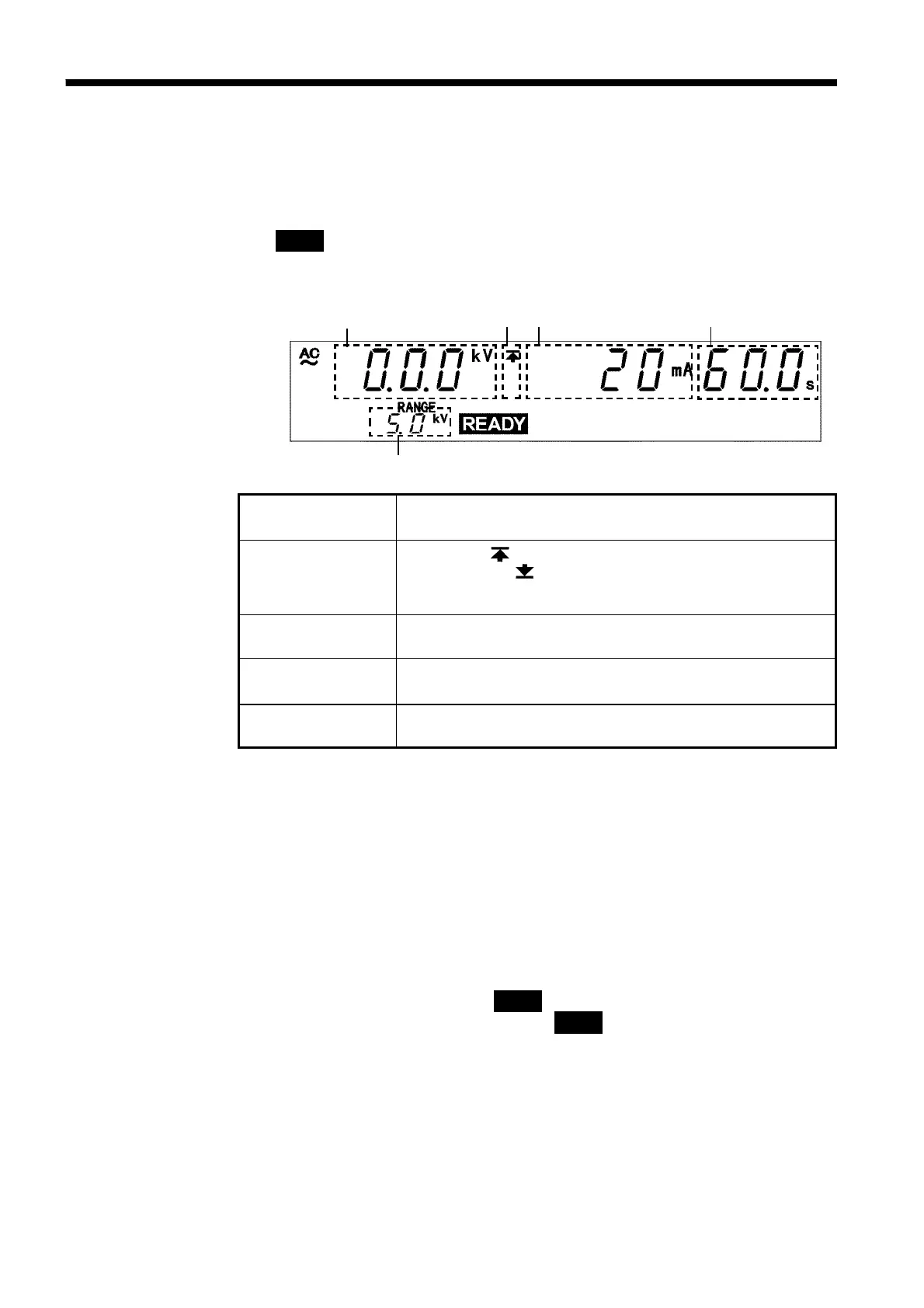
3.2 Displaying the READY State
______________________________________________________________________________________________
1 2 3 4
5
1 Measured
voltage value
Indicates the voltage value being output. In the READY
state, the value indicates at 0 kV.
2 Upper limit value
icon
Lower limit value
icon
The symbol appears when the upper limit value is set,
and the symbol
appears when the lower limit value is
set.
3 Upper (Lower)
limit value
Indicates Upper (Lower) limit value.
4 Test time
Indicates the preset test time. "
OFF
" is indicated when no
test-time setting has been made.
5 Output voltage
range
Indicates the output-voltage range.
3.2 Displaying the READY State
In the READY state, the unit is always ready to start a test. The unit can be
shifted to the SETTING state only when it is in the READY state.
The
READY
lamp remains lit to indicate the READY state.
Saving and loading for setting data and the setting of optional functions are
made following the READY state.
Danger lamp
Indicates that a voltage is being output. This lamp remains lit as long as a
voltage is being applied to the output terminal. It does not light up in the
READY state.
Analog voltmeter
Indicates the voltage value being output. In the READY state, the value
remains at 0 kV.
External I/O
The
READY
――――――――――
signal is ON when
READY
is lit on the fluorescent indicator.
The
READY
――――――――――
signal is turned OFF when
READY
is not lit.